Subaru Legacy IV (2008 year). Service manual — part 988
AC(diag)-4
General Description
HVAC SYSTEM (AUTO A/C) (DIAGNOSTICS)
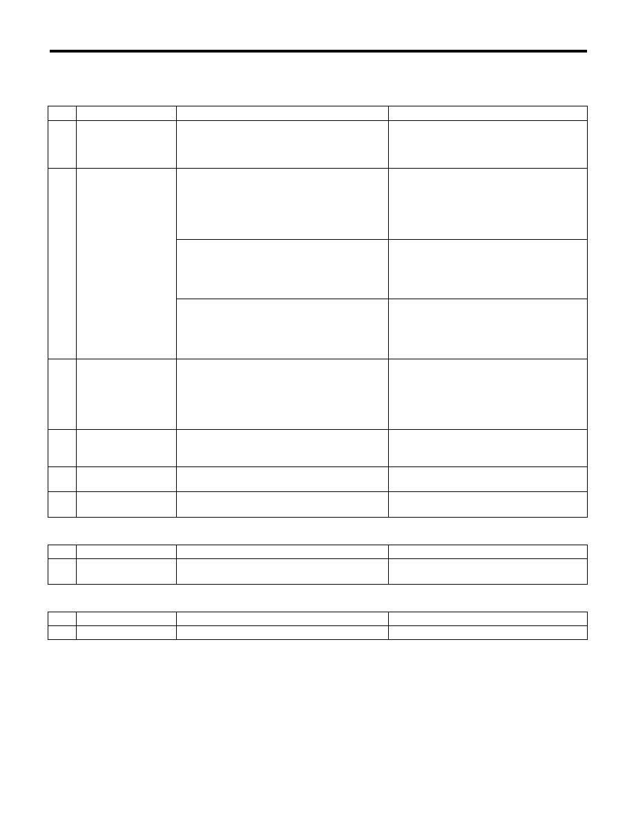
5. CONTROL SWITCHES
Start the engine and warm up completely.
1) Inspection using switches
2) Inspection of compressor operation
3) Inspection of illumination control
No.
Point to check
Switch operation
Judgement standard
1
OFF switch
Press the OFF switch.
Setting temperature display goes out.
• Blower fan: OFF
• Inlet opening: FRESH
• Compressor: OFF
2
AUTO switch, driver’s
side temperature con-
trol dial and passen-
ger’s side temperature
control dial
1) Press the AUTO switch.
2) Turn the temperature control dial to the left
fully, and set to 18°C (65°F) (maximum cool posi-
tion).
AUTO display illuminates.
• Outlet air temperature: COOL
• Blower fan: HI (AUTO)
• Outlet opening: FACE
• Inlet opening: AUTO
• Compressor: AUTO
3) Turn the temperature control dial to the right
slowly, and change the setting from 18°C (65°F)
(maximum cool position) to 32°C (85°F).
• Outlet air temperature: COOL
o HOT
• Blower fan: AUTO
• Outlet opening: FACE
o B/L o FOOT
• Inlet opening: AUTO
• Compressor: AUTO
4) Turn the temperature control dial to the right
fully, and set to 32°C (85°F) (maximum hot posi-
tion).
• Outlet air temperature: HOT
• Blower fan: HI (AUTO)
• Outlet opening: FOOT
• Inlet opening: FRESH (AUTO)
• Compressor: AUTO
3
Defroster switch
Press the defroster switch.
Defroster switch indicator illuminates.
• Outlet air temperature: AUTO
• Blower fan: AUTO
• Outlet opening: DEF
• Inlet opening: FRESH
• Compressor: ON
4
FRESH/RECIRC
switch
Press the FRESH/RECIRC switch.
Inlet opening switches RECIRC
o FRESH or
FRESH
o RECIRC each time pressing the
switch.
5
MODE switch
Press the MODE switch.
Outlet opening switches FACE
o B/L o
FOOT
o F/D each time pressing the switch.
6
FAN switch
Press the FAN switch (+).
Inlet opening switches LO
o M1 o M2 o M3
o M4 o HI each time pressing the switch.
No.
Point to check
Switch operation
Judgement standard
1
Compressor
1) Turn the A/C switch to ON.
2) Set the FAN switch between LO and HI.
Compressor: ON
No.
Point to check
Switch operation
Judgement standard
1
Illumination
Turn the lighting switch to ON.
Illumination comes on.
AC(diag)-5
Electrical Component Location
HVAC SYSTEM (AUTO A/C) (DIAGNOSTICS)
3. Electrical Component Location
A: LOCATION
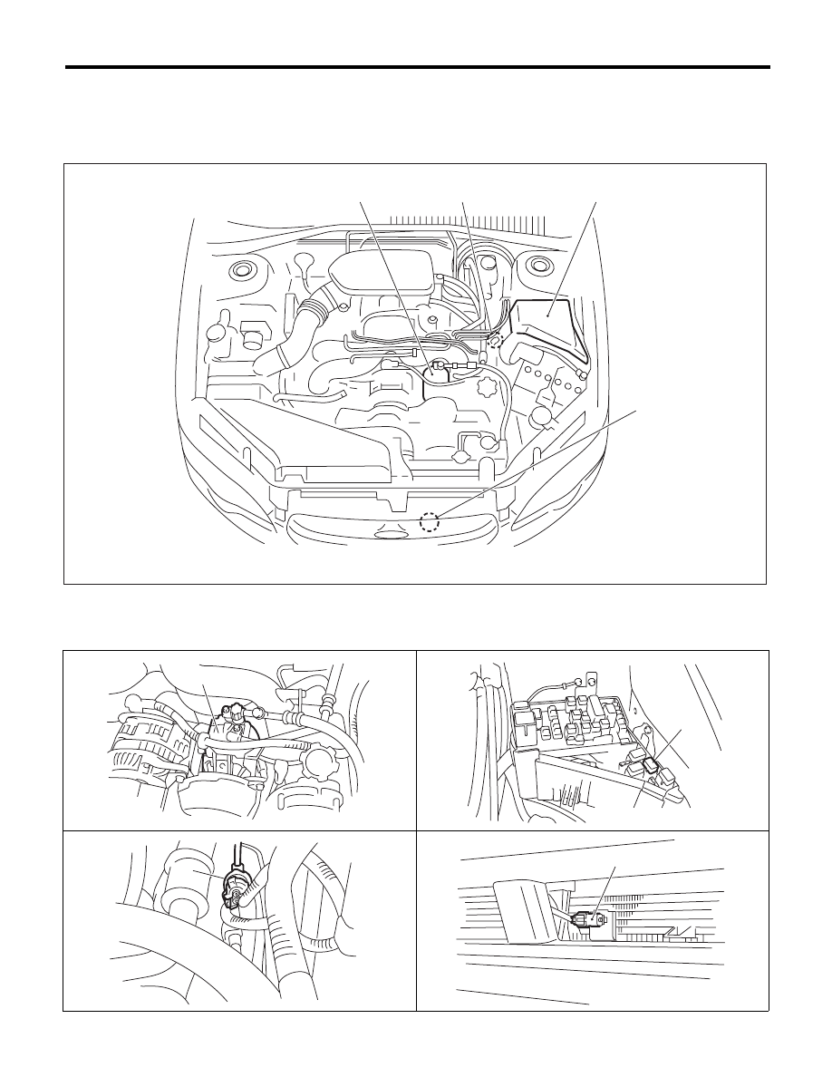
1. ENGINE COMPARTMENT
(1)
A/C compressor
(3)
Pressure switch
(4)
Ambient sensor
(2)
A/C
relay
AC-00896
(2)
(4)
(1)
(3)
AC-00813
(1)
(2)
AC-01603
AC-00814
(3)
AC-00816
(4)
AC(diag)-6
Electrical Component Location
HVAC SYSTEM (AUTO A/C) (DIAGNOSTICS)
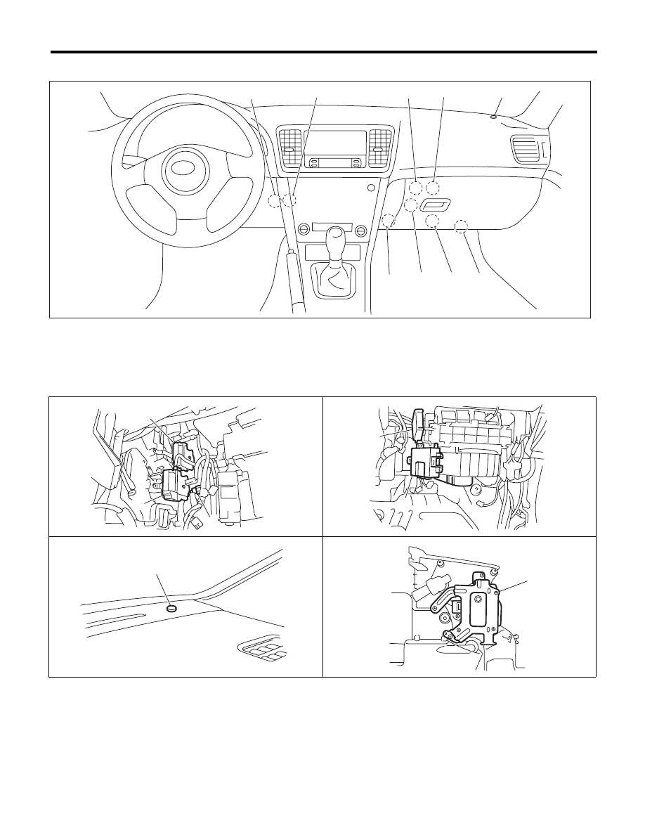
2. PASSENGER COMPARTMENT
(1)
Evaporator sensor
(4)
Blower motor
(7)
Mode door actuator
(2)
Passenger’s side air mix door
actuator
(5)
Sunload sensor
(8)
In-vehicle sensor
(6)
Intake door actuator
(9)
Driver’s side air mix door actuator
(3)
Auto A/C control module
(7)
(6)
(4)
(3)
(2)
(1)
(5)
(9)
(8)
AC-01595
AC-00898
(1)
(2)
(7)
(3)
(4)
(6)
AC-00900
AC-00899
(5)
AC-01164
(9)
AC(diag)-7
Auto A/C Control Module I/O Signal
HVAC SYSTEM (AUTO A/C) (DIAGNOSTICS)
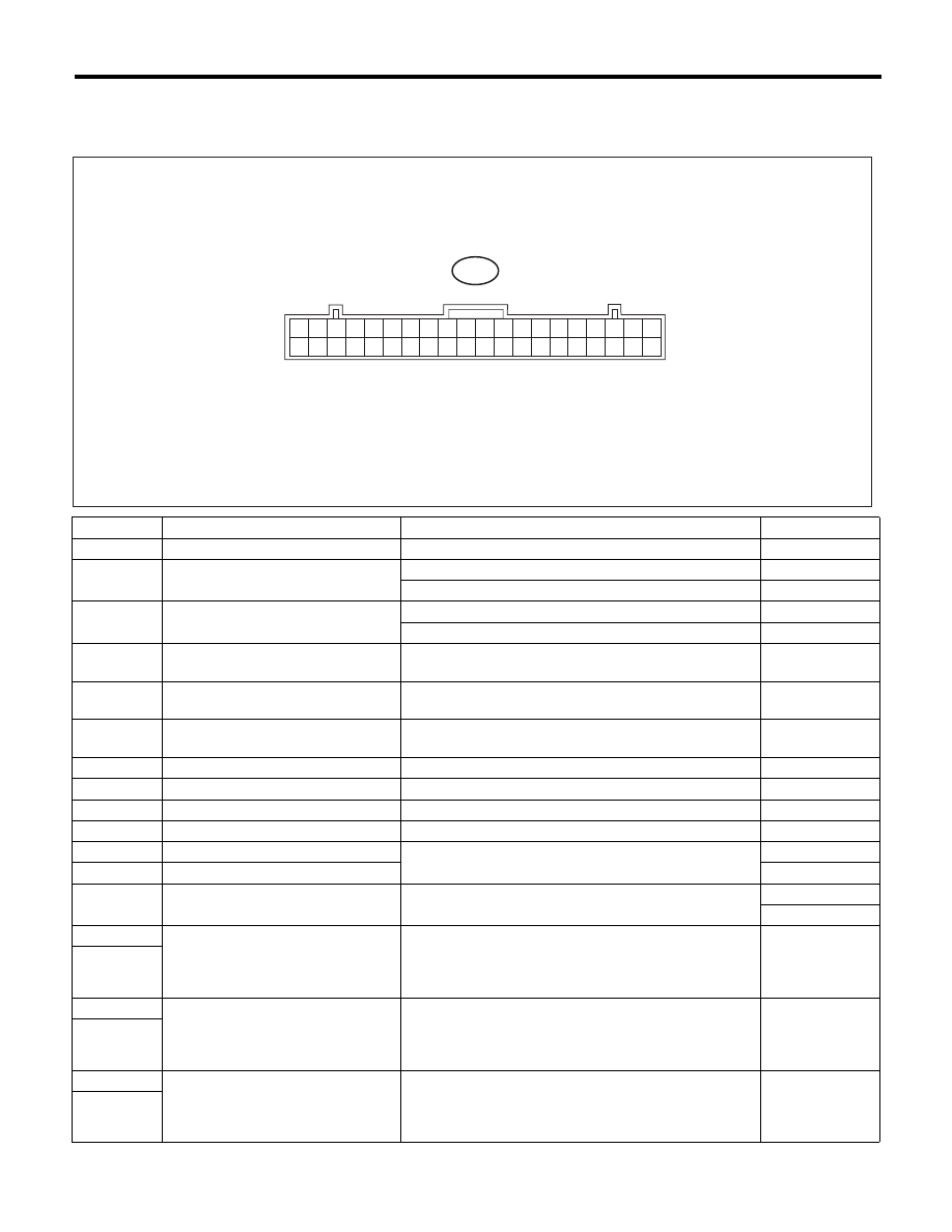
4. Auto A/C Control Module I/O Signal
A: ELECTRICAL SPECIFICATION
Terminal No.
Remarks
Measuring condition
Standard
1
Battery power supply
Ignition switch: OFF
Battery voltage
3
Mode door actuator position signal
Mode door: FACE position
4 V
Mode door: DEF position
1 V
4
Air mix door actuator (passenger’s
side) position signal
Air mix door: Maximum cool position
4 V
Air mix door: Maximum hot position
1 V
5
In-vehicle sensor
Ignition switch: ON
25°C: 1 — 5 V
40°C: 1 — 5 V
6
Sunload sensor
Ignition switch: ON, With Sunload (No sunload: 0 V)
Sunlight: 3 V
Room light: 3 V
8
Each potentiometer and sunload
sensor power supply
Ignition switch: ON
5 V
9
CAN LO
—
*1
10
CAN HI
—
*1
11
Blower motor voltage feedback
Ignition switch : ON, Blower switch : ON
0.45 — 10 V
12
Blower motor control signal
Ignition switch : ON, Blower switch : ON
9.05 V
13
RAM monitor Tx
Outputs RAM value when No. 33 (RAMver) terminal is
grounded
*1
14
RAM monitor Rx
*1
15
Magnet clutch ON request signal
output sensor ground
Ignition switch: ON, Blower switch: ON, A/C switch: ON
HI: 5.5 V
LO: 2.0 V
16
Mode servo drive signal
When actuator is operating
16(+) — 36(–): Turns towards FACE side
16 (–) — 36 (+): rotate to the DEF side
16-36 short: brake
0 or 12 V
36
17
Air mix door actuator (passenger’s
side) drive signal
When actuator is operating
17(+) — 37(–): Turns towards COOL side
17 (–) — 37 (+): rotate to the HOT side
17-37 short: brake
0 or 12 V
37
18
Air mix door actuator (driver’s seat)
When actuator is operating
18(+) — 38(–): Turns towards COOL side
18 (–) — 38 (+): rotate to the HOT side
18-38 short: brake
0 or 12 V
38
B282
1
2
3
4
5
6
7
8
9
10
11
12
13
14
15
16
17
18
19
20
21
22
23
24
25
26
27
28
29
30
31
32
33
34
35
36
37
38
39
40
AC-01515
Нет комментариевНе стесняйтесь поделиться с нами вашим ценным мнением.
Текст