Subaru Legacy IV (2008 year). Service manual — part 987

AC-51
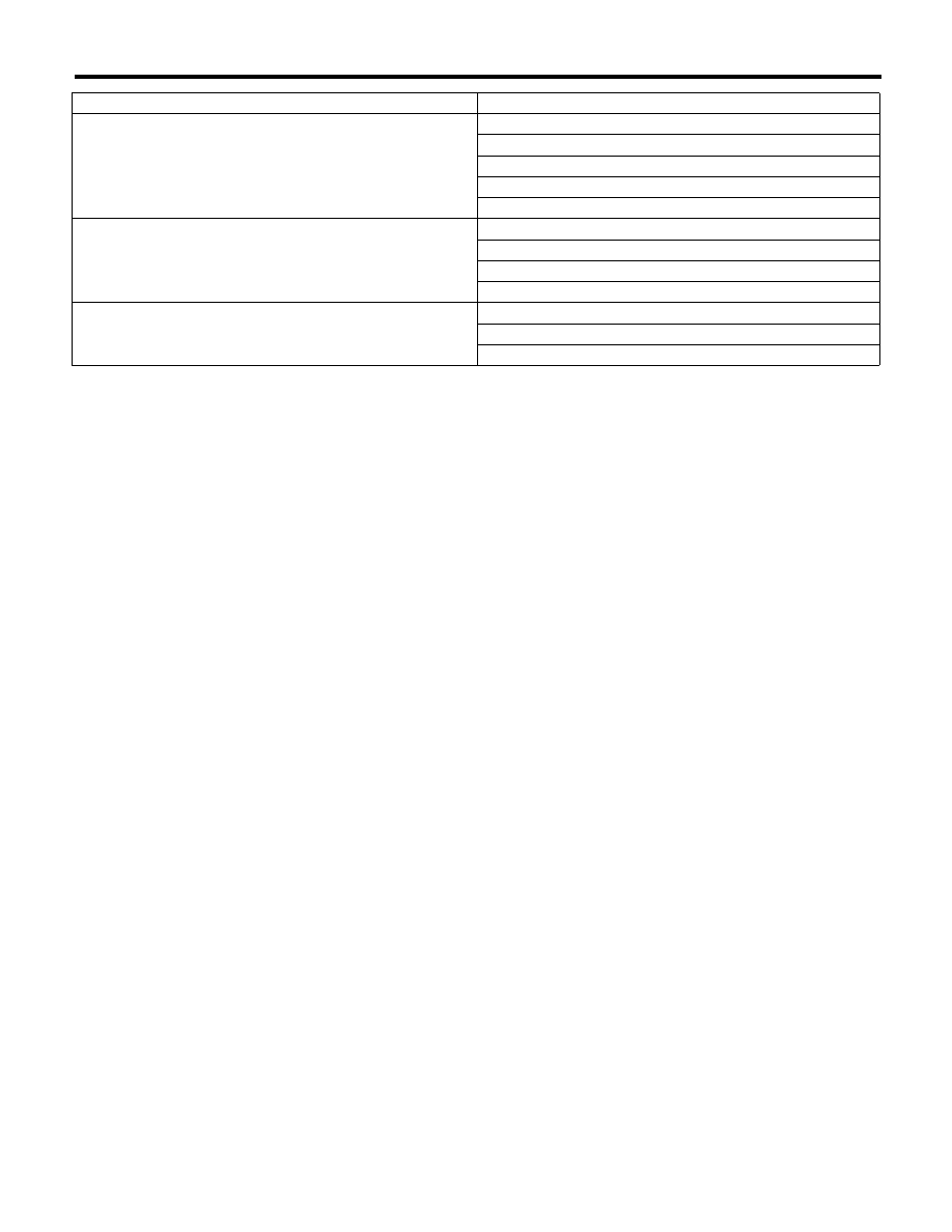
General Diagnostic Table
HVAC SYSTEM (HEATER, VENTILATOR AND A/C)
30.General Diagnostic Table
A: INSPECTION
Symptoms
Repair order
Blower motor
Does not operate.
Fuse
Blower motor relay
Blower motor
Blower motor resistor (Manual A/C)
Blower switch
Wiring harness
Strange noise
Blower motor
Compressor
Does not operate.
Refrigerant
Fuses
Air conditioning relay
Magnet clutch
Compressor
Pressure switch
A/C switch
Blower switch
Wiring harness
Strange noise
V-belt
Magnet clutch
Compressor
Belt tension adjuster
Cold air not emitted.
Refrigerant
V-belt
Magnet clutch
Compressor
Pressure switch
Aspirator hose (Auto A/C)
Blower fan relay
Blower motor
A/C switch
Blower switch
Control module
Expansion valve
Evaporator
Air mix actuator (Auto A/C)
Temperature control cable (Manual A/C)
Wiring harness
Heater duct
Heater vent duct
Warm air not emitted.
Engine coolant
Aspirator hose (Auto A/C)
Air mix actuator (Auto A/C)
Temperature control cable (Manual A/C)
Blower switch
Heater core
AC-52
General Diagnostic Table
HVAC SYSTEM (HEATER, VENTILATOR AND A/C)
Temperature of air from vents does not change.
Engine coolant
Air mix actuator (Auto A/C)
Temperature control cable (Manual A/C)
Temperature control switch (Auto A/C)
Wiring harness (Auto A/C)
Unable to switch blow vents.
Mode actuator (Auto A/C)
Mode switch cable (Manual A/C)
Mode switch (Auto A/C)
Wiring harness (Auto A/C)
Unable to switch suction vents.
FRESH/RECIRC switch (Auto A/C)
FRESH/RECIRC actuator (Auto A/C)
Wiring harness (Auto A/C)
Symptoms
Repair order

AC(diag)-2
Basic Diagnostic Procedure
HVAC SYSTEM (AUTO A/C) (DIAGNOSTICS)
1. Basic Diagnostic Procedure
A: PROCEDURE
Step
Check
Yes
No
1
START INSPECTIONS.
1) Perform the pre-inspection. <Ref. to
AC(diag)-3, INSPECTION, General Descrip-
tion.>
2) Perform the self-diagnosis. <Ref. to
AC(diag)-9, OPERATION, Diagnostic Chart for
Self-Diagnosis.>
Does the self-diagnosis oper-
ate?
Go to step 2.
<Ref. to AC(diag)-
14, A/C OR SELF-
DIAGNOSIS SYS-
TEMS DO NOT
OPERATE, Diag-
nostics for A/C
System Malfunc-
tion.>
2
IDENTIFY MALFUNCTION PART.
Identify the malfunction part with self-diagnosis.
Can the malfunction part be
confirmed?
Repair the mal-
functioning part in
accordance with
each diagnostic
chart.
Go to step 3.
3
CHECK COMPARTMENT TEMPERATURE.
1) Turn on the A/C switch.
2) Turn the temperature control dial at maxi-
mum cool position.
3) Check the compartment temperature
change.
Does the compartment temper-
ature change?
Go to step 4.
<Ref. to AC(diag)-
18, COMPART-
MENT TEMPERA-
TURE DOES NOT
CHANGE, OR A/C
SYSTEM DOES
NOT RESPOND
PROMPTLY, Diag-
nostics for A/C
System Malfunc-
tion.>
4
CHECK A/C SYSTEM RESPONSE.
Change the temperature setting, and check the
response of A/C system.
Does the A/C system respond
quickly?
A/C system is nor-
mal.
<Ref. to AC(diag)-
18, COMPART-
MENT TEMPERA-
TURE DOES NOT
CHANGE, OR A/C
SYSTEM DOES
NOT RESPOND
PROMPTLY, Diag-
nostics for A/C
System Malfunc-
tion.>
AC(diag)-3
General Description
HVAC SYSTEM (AUTO A/C) (DIAGNOSTICS)
2. General Description
A: CAUTION
1) Never connect the battery in reverse polarity.
Doing so may immediately damage the auto A/C
control module.
2) Do not disconnect the battery terminals while the
engine is running. A large counter electromotive
force will be generated in the generator, and this
voltage may damage electronic parts such as auto
A/C control module etc.
3) Before disconnecting the connectors of sensors
and the auto A/C control module, be sure to turn off
the ignition switch. Auto A/C control module may be
damaged.
4) Every A/C-related part is a precision part. Do not
drop them.
5) Airbag system wiring harness is routed near the
A/C control panel and junction box.
CAUTION:
• Do not use electrical test equipment on wir-
ing harness and connector circuits of the air-
bag system.
• Be careful not to damage the airbag system
wiring harness when servicing the A/C control
panel and junction box.
B: INSPECTION
Before performing the diagnosis, check the follow-
ing items which may cause problems in the A/C
system.
1. BATTERY
1) Measure the battery voltage and specific gravity
of electrolyte.
Standard voltage: 12 V
Specific gravity: 1.260 or more
2) Check the condition of the fuses for A/C system
power supply and other fuses.
3) Check the condition of harness and harness
connector connections.
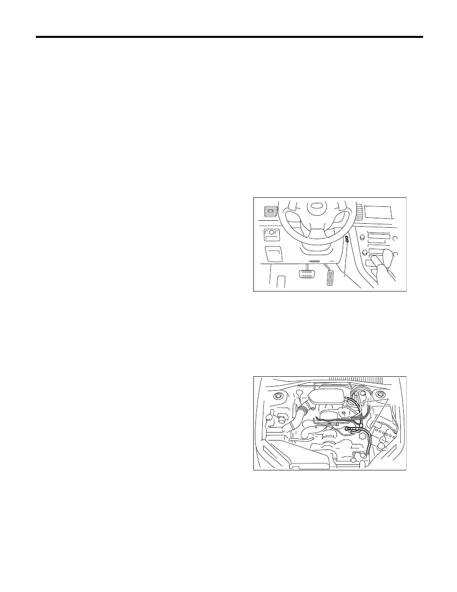
2. ASPIRATOR HOSE
1) Turn the ignition switch to ON, and press the A/
C switch.
2) Turn the temperature control dial to maximum
hot position.
3) Turn the air flow control dial to “DEF” position.
4) Turn the fan speed control dial to “MAX” posi-
tion.
5) Put a strip of paper close to the front side of in-
vehicle sensor suction port (A) located in the driv-
er’s side console side panel, and check that air is
being sucked into the port by seeing the paper
moving towards the port.
NOTE:
Be careful not to let the paper get sucked into the
port.
6) If the paper does not move at all, remove the
driver’s side console side panel <Ref. to EI-55, RE-
MOVAL, Center Console.> and check for improper
connection of the aspirator hose, in-vehicle sensor
and heater unit, and repair them if necessary.
3. A/C LINE
Check the connection for A/C line (A) and lower
side high-pressure pipe.
4. CONTROL LINKAGE
1) Check the state of mode door linkage.
2) Check the state of air mix door linkage.
3) Check the state of FRESH/RECIRC door link-
age.
AC-01188
(A)
(A)
AC-00895
Нет комментариевНе стесняйтесь поделиться с нами вашим ценным мнением.
Текст