Subaru Legacy IV (2008 year). Service manual — part 376
EN(H4DOTC)(diag)-325
Diagnostic Procedure with Diagnostic Trouble Code (DTC)
ENGINE (DIAGNOSTICS)
DS:DTC P2103 THROTTLE ACTUATOR CONTROL MOTOR CIRCUIT HIGH
DTC DETECTING CONDITION:
• Immediately at fault recognition
• GENERAL DESCRIPTION <Ref. to GD(H4DOTC)-210, DTC P2103 THROTTLE ACTUATOR CONTROL
MOTOR CIRCUIT HIGH, Diagnostic Trouble Code (DTC) Detecting Criteria.>
CAUTION:
After repair or replacement of faulty parts, perform Clear Memory Mode <Ref. to EN(H4DOTC)(diag)-
52, OPERATION, Clear Memory Mode.>, and Inspection Mode <Ref. to EN(H4DOTC)(diag)-43, PRO-
CEDURE, Inspection Mode.>.
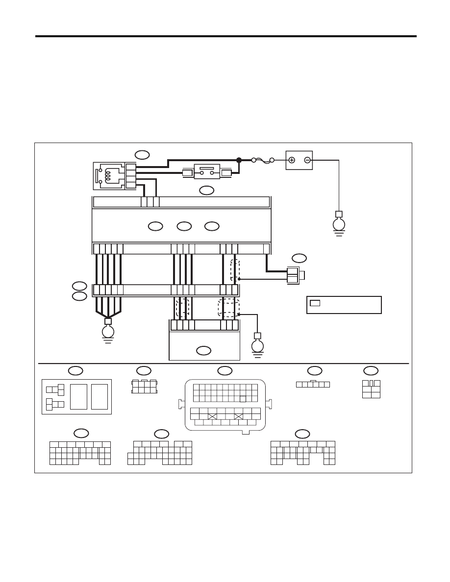
WIRING DIAGRAM:
EN-05673
5
6
7
8
2
1
9
4
3
10
24
22 23
25
11 12 13 14 15
26 27
28
16 17
18 19 20 21
33 34
29
32
30 31
1 2
7 8
3
4
5
6
1 2 3 4 5 6 7 8 9 10 11
12 13 14 15 16 17 18 19 20 21 22
23 24 25
34 35
36 37 38 39 40 41
48 49
50 51 52 53 54
42 43
44 45
46 47
26 27 28 29 30 31 32 33
1 2 3 4
5 6 7 8
1
2
7
8 9
5
6
3
4
10 11 12
19 20 21
29
30 31
13 14 15 16 17
27
28
18
22 23
24 25
26
1
2
8 9
5
6
3
4
10 11 12
19 20 21
29 30
31
13 14 15 16
17
27
28
18
22 23 24 25 26
7
32 33 34 35
1 2 3 4 5 6
E57
B47
B137
D:
B21
B122
B136
C:
B362
B134
A:
36
40
34
35
37
E2
B21
C21
C1
A29
6
A18
C6
A28
6
4
25
*
*
B122
24
E
38
39
28
D5
D4
A19
A5
D7
D1
D2
D3
3
E57
2
1
5
B134
B362
B47
5
7
6
A:
B137
B136
D:
C:
*
E
SBF-7
8
6
4
E
3
4
1
2
5
6
ELECTRONIC
THROTTLE
CONTROL RELAY
MAIN RELAY
BATTERY
ECM
ELECTRONIC THROTTLE
CONTROL
: TERMINAL No. OPTIONAL
ARRANGEMENT

EN(H4DOTC)(diag)-326
Diagnostic Procedure with Diagnostic Trouble Code (DTC)
ENGINE (DIAGNOSTICS)
DT:DTC P2109 THROTTLE/PEDAL POSITION SENSOR “A” MINIMUM STOP
PERFORMANCE
NOTE:
For the diagnostic procedure, refer to DTC P2101. <Ref. to EN(H4DOTC)(diag)-318, DTC P2101 THROT-
TLE ACTUATOR CONTROL MOTOR CIRCUIT RANGE/PERFORMANCE, Diagnostic Procedure with Di-
agnostic Trouble Code (DTC).>
Step
Check
Yes
No
1
CHECK ELECTRONIC THROTTLE CON-
TROL RELAY.
1) Turn the ignition switch to OFF.
2) Remove the electronic throttle control relay.
3) Measure the resistance between electronic
throttle control relay terminals.
Terminals
No. 7 — No. 8:
Is the resistance 1 M
: or
more?
Go to step 2.
Replace the elec-
tronic throttle con-
trol relay. <Ref. to
FU(H4DOTC)-55,
Electronic Throttle
Control Relay.>
2
CHECK SHORT CIRCUIT OF ELECTRONIC
THROTTLE CONTROL RELAY POWER SUP-
PLY.
1) Turn the ignition switch to ON.
2) Measure the voltage between electronic
throttle control relay connector and chassis
ground.
Connector & terminal
(B362) No. 8 (+) — Chassis ground (–):
Is the voltage 10 V or more?
Repair the short
circuit to power in
harness between
ECM and elec-
tronic throttle con-
trol relay.
Go to step 3.
3
CHECK HARNESS BETWEEN ECM AND
ELECTRONIC THROTTLE CONTROL RE-
LAY.
1) Turn the ignition switch to OFF.
2) Disconnect the connectors from ECM.
3) Measure the resistance between ECM and
chassis ground.
Connector & terminal
(B136) No. 21 — Chassis ground:
Is the resistance 1 M
: or
more?
Repair the poor
contact of ECM
connector.
Repair the ground
short circuit of har-
ness between
ECM and elec-
tronic throttle con-
trol relay.
EN(H4DOTC)(diag)-327
Diagnostic Procedure with Diagnostic Trouble Code (DTC)
ENGINE (DIAGNOSTICS)
DU:DTC P2122 THROTTLE/PEDAL POSITION SENSOR/SWITCH “D” CIRCUIT
LOW INPUT
DTC DETECTING CONDITION:
• Immediately at fault recognition
• GENERAL DESCRIPTION <Ref. to GD(H4DOTC)-214, DTC P2122 THROTTLE/PEDAL POSITION
SENSOR/SWITCH “D” CIRCUIT LOW INPUT, Diagnostic Trouble Code (DTC) Detecting Criteria.>
TROUBLE SYMPTOM:
• Improper idling
• Poor driving performance
CAUTION:
After repair or replacement of faulty parts, perform Clear Memory Mode <Ref. to EN(H4DOTC)(diag)-
52, OPERATION, Clear Memory Mode.>, and Inspection Mode <Ref. to EN(H4DOTC)(diag)-43, PRO-
CEDURE, Inspection Mode.>.
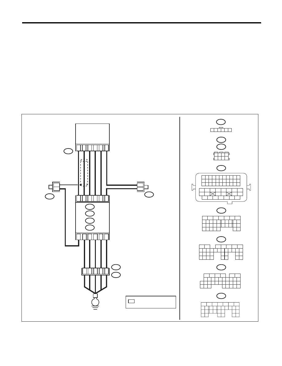
WIRING DIAGRAM:
EN-05690
B315
C: B136
B137
D:
B83
B315
*
*
4
6
5
1
3
2
B21
B23
B29
B22
B31
B30
D2
B21
E2
D1
1 2 3 4
5 6 7 8
B21
1 2 3 4
12 13 14 15
5 6 7 8
16 17 18 19
9 10 11
20 21 22
23 24 25 26 27 28 29 30 31 32 33
35
34
37
36
39
38
41
40
43
42
44
45
47
46
49
48
51
50
53
52
54
B137
5
6
7
8
2
1
9
4
3
10
22 23
11 12 13 14 15
24 25
26
16 17
18 19 20 21
27
28 29
30 31
B136
5
6
7 8
2
1
9
4
3
10
24
22 23
25
11 12 13 14 15
26 27
28
16
17 18 19 20 21
33 34
29
32
30
31
35
B135
5
6
7
8
2
1
9
4
3
10
24
22 23
25
11 12 13 14 15
26 27
28
16 17 18 19
20 21
29 30 31
32 33
34 35
B:
C:
D:
B122
B83
D3
A5
C6
B: B135
A: B134
D7
37
35
34
40
36
B122
1 2 3 4 5 6
*
*
B134
5
6
7
8
2
1
9
4
3
10
24
22 23
25
11 12 13 14 15
26 27
28
16 17
18 19 20 21
33 34
29
32
30 31
A:
E
*
ACCELERATOR PEDAL
POSITION SENSOR
ECM
: TERMINAL No. OPTIONAL
ARRANGEMENT

EN(H4DOTC)(diag)-328
Diagnostic Procedure with Diagnostic Trouble Code (DTC)
ENGINE (DIAGNOSTICS)
Step
Check
Yes
No
1
CHECK HARNESS BETWEEN ECM AND AC-
CELERATOR PEDAL POSITION SENSOR.
1) Turn the ignition switch to OFF.
2) Disconnect the connector from ECM and
accelerator pedal position sensor.
3) Measure the resistance between ECM and
chassis ground.
Connector & terminal
(B135) No. 21 — Chassis ground:
(B135) No. 23 — Chassis ground:
(B135) No. 23 — (B136) No. 6:
Is the resistance 1 M
: or
more?
Go to step 2.
Repair the ground
short circuit of har-
ness between
ECM and accelera-
tor pedal position
sensor connector.
2
CHECK SHORT CIRCUIT INSIDE THE ECM.
1) Connect the ECM.
2) Measure the resistance between accelera-
tor pedal position sensor connector and chassis
ground.
Connector & terminal
(B315) No. 6 — Chassis ground:
Is the resistance 1 M
: or
more?
Replace the accel-
erator pedal. <Ref.
to SP(H4SO)-3,
Accelerator
Pedal.>
Repair the ground
short circuit of har-
ness between
ECM and accelera-
tor pedal position
sensor connector.
Replace the ECM if
defective. <Ref. to
FU(H4DOTC)-52,
Engine Control
Module (ECM).>
Нет комментариевНе стесняйтесь поделиться с нами вашим ценным мнением.
Текст