Subaru Legacy IV (2008 year). Service manual — part 374

EN(H4DOTC)(diag)-317
Diagnostic Procedure with Diagnostic Trouble Code (DTC)
ENGINE (DIAGNOSTICS)
19
CHECK HARNESS BETWEEN ECM AND
REAR OXYGEN SENSOR CONNECTOR.
1) Turn the ignition switch to OFF.
2) Disconnect the connectors from ECM and
rear oxygen sensor.
3) Measure the resistance of harness between
ECM and rear oxygen sensor connector.
Connector & terminal
(B135) No. 4 — (T6) No. 3:
(B135) No. 30 — (T6) No. 4:
Is the resistance less than 1
:? Go to step 20.
Repair the harness
and connector.
NOTE:
In this case, repair
the following item:
• Open circuit in
harness between
ECM and rear oxy-
gen sensor con-
nector
• Poor contact of
coupling connector
20
CHECK HARNESS BETWEEN ECM AND
REAR OXYGEN SENSOR CONNECTOR.
1) Connect the connector to ECM.
2) Turn the ignition switch to ON.
3) Measure the voltage between rear oxygen
sensor connector and chassis ground.
Connector & terminal
(T6) No. 3 (+) — Chassis ground (–):
Is the voltage 0.2 — 0.5 V?
Replace the rear
oxygen sensor.
<Ref. to
FU(H4DOTC)-48,
Rear Oxygen Sen-
sor.>
Repair the harness
and connector.
NOTE:
In this case, repair
the following item:
• Open circuit of
harness between
the ECM and rear
oxygen sensor
• Poor contact in
ECM connector
• Poor contact of
coupling connector
Step
Check
Yes
No
EN(H4DOTC)(diag)-318
Diagnostic Procedure with Diagnostic Trouble Code (DTC)
ENGINE (DIAGNOSTICS)
DQ:DTC P2101 THROTTLE ACTUATOR CONTROL MOTOR CIRCUIT RANGE/
PERFORMANCE
DTC DETECTING CONDITION:
• Immediately at fault recognition
• GENERAL DESCRIPTION <Ref. to GD(H4DOTC)-206, DTC P2101 THROTTLE ACTUATOR CONTROL
MOTOR CIRCUIT RANGE/PERFORMANCE, Diagnostic Trouble Code (DTC) Detecting Criteria.>
TROUBLE SYMPTOM:
• Improper idling
• Poor driving performance
• Engine stalls.
CAUTION:
After repair or replacement of faulty parts, perform Clear Memory Mode <Ref. to EN(H4DOTC)(diag)-
52, OPERATION, Clear Memory Mode.>, and Inspection Mode <Ref. to EN(H4DOTC)(diag)-43, PRO-
CEDURE, Inspection Mode.>.
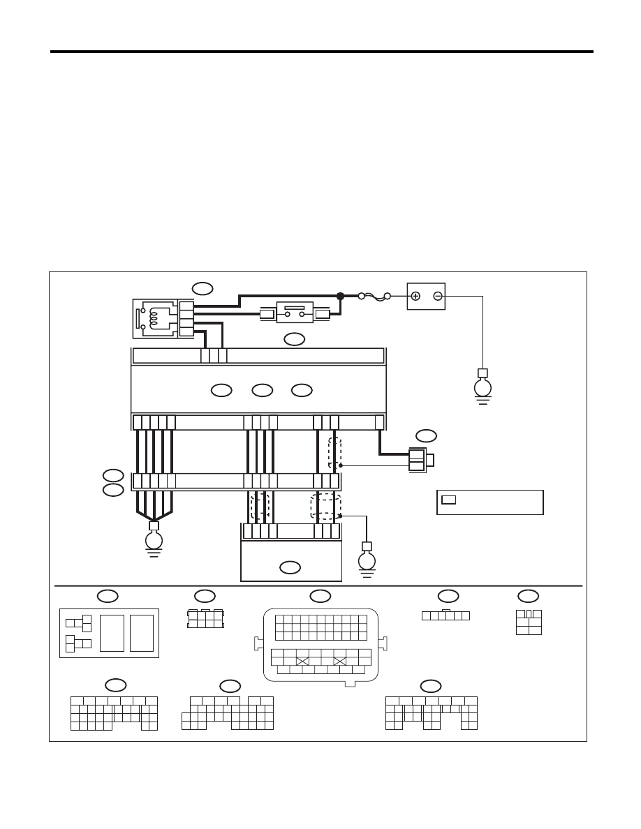
WIRING DIAGRAM:
EN-05673
5
6
7
8
2
1
9
4
3
10
24
22 23
25
11 12 13 14 15
26 27
28
16 17
18 19 20 21
33 34
29
32
30 31
1 2
7 8
3
4
5
6
1 2 3 4 5 6 7 8 9 10 11
12 13 14 15 16 17 18 19 20 21 22
23 24 25
34 35
36 37 38 39 40 41
48 49
50 51 52 53 54
42 43
44 45
46 47
26 27 28 29 30 31 32 33
1 2 3 4
5 6 7 8
1
2
7
8 9
5
6
3
4
10 11 12
19 20 21
29
30 31
13 14 15 16 17
27
28
18
22 23
24 25
26
1
2
8 9
5
6
3
4
10 11 12
19 20 21
29 30
31
13 14 15 16
17
27
28
18
22 23 24 25 26
7
32 33 34 35
1 2 3 4 5 6
E57
B47
B137
D:
B21
B122
B136
C:
B362
B134
A:
36
40
34
35
37
E2
B21
C21
C1
A29
6
A18
C6
A28
6
4
25
*
*
B122
24
E
38
39
28
D5
D4
A19
A5
D7
D1
D2
D3
3
E57
2
1
5
B134
B362
B47
5
7
6
A:
B137
B136
D:
C:
*
E
SBF-7
8
6
4
E
3
4
1
2
5
6
ELECTRONIC
THROTTLE
CONTROL RELAY
MAIN RELAY
BATTERY
ECM
ELECTRONIC THROTTLE
CONTROL
: TERMINAL No. OPTIONAL
ARRANGEMENT

EN(H4DOTC)(diag)-319
Diagnostic Procedure with Diagnostic Trouble Code (DTC)
ENGINE (DIAGNOSTICS)
Step
Check
Yes
No
1
CHECK ELECTRONIC THROTTLE CON-
TROL RELAY.
1) Turn the ignition switch to OFF.
2) Remove the electronic throttle control relay.
3) Connect the battery to terminals No. 5 and
No. 6 of electronic throttle control relay.
4) Measure the resistance between electronic
throttle control relay terminals.
Terminals
No. 7 — No. 8:
Is the resistance less than 1
:? Go to step 2.
Replace the elec-
tronic throttle con-
trol relay. <Ref. to
FU(H4DOTC)-55,
Electronic Throttle
Control Relay.>
2
CHECK POWER SUPPLY OF ELECTRONIC
THROTTLE CONTROL RELAY.
Measure the voltage between electronic throttle
control relay connector and chassis ground.
Connector & terminal
(B362) No. 7 (+) — Chassis ground (–):
Is the voltage 10 V or more?
Go to step 3.
Repair the open or
ground short circuit
of power supply
circuit.
3
CHECK HARNESS BETWEEN ECM AND
ELECTRONIC THROTTLE CONTROL RE-
LAY.
1) Disconnect the connectors from ECM.
2) Turn the ignition switch to ON.
3) Measure the voltage between electronic
throttle control relay connector and chassis
ground.
Connector & terminal
(B362) No. 6 (+) — Chassis ground (–):
Is the voltage 10 V or more?
Repair the short
circuit to power in
harness between
ECM and elec-
tronic throttle con-
trol relay.
Go to step 4.
4
CHECK HARNESS BETWEEN ECM AND
ELECTRONIC THROTTLE CONTROL RE-
LAY.
1) Turn the ignition switch to OFF.
2) Measure the resistance between electronic
throttle control relay connector and chassis
ground.
Connector & terminal
(B362) No. 6 — Chassis ground:
(B362) No. 8 — Chassis ground:
Is the resistance 1 M
: or
more?
Go to step 5.
Repair the ground
short circuit of har-
ness between
ECM and elec-
tronic throttle con-
trol relay.
5
CHECK HARNESS BETWEEN ECM AND
ELECTRONIC THROTTLE CONTROL RE-
LAY.
Measure the resistance between ECM and
electronic throttle control relay connector.
Connector & terminal
(B136) No. 21 — (B362) No. 6:
(B136) No. 1 — (B362) No. 8:
Is the resistance less than 1
:? Go to step 6.
Repair the open
circuit of harness
between ECM and
electronic throttle
control relay.
6
CHECK HARNESS BETWEEN ECM AND
ELECTRONIC THROTTLE CONTROL.
1) Turn the ignition switch to OFF.
2) Disconnect the connectors from electronic
throttle control.
3) Measure the resistance between ECM and
chassis ground.
Connector & terminal
(B134) No. 19 — Chassis ground:
(B134) No. 18 — Chassis ground:
(B134) No. 18 — (B136) No. 6:
(B134) No. 28 — Chassis ground:
Is the resistance 1 M
: or
more?
Go to step 7.
Repair the short
circuit to ground in
harness between
ECM and elec-
tronic throttle con-
trol connector.

EN(H4DOTC)(diag)-320
Diagnostic Procedure with Diagnostic Trouble Code (DTC)
ENGINE (DIAGNOSTICS)
7
CHECK SHORT CIRCUIT INSIDE THE ECM.
1) Connect the ECM.
2) Measure the resistance between electronic
throttle control connector and engine ground.
Connector & terminal
(E57) No. 6 — Engine ground:
(E57) No. 4 — Engine ground:
Is the resistance 1 M
: or
more?
Go to step 8.
Repair the short
circuit to ground in
harness between
ECM and elec-
tronic throttle con-
trol connector.
Replace the ECM if
defective. <Ref. to
FU(H4DOTC)-52,
Engine Control
Module (ECM).>
8
CHECK HARNESS BETWEEN ECM AND
ELECTRONIC THROTTLE CONTROL.
1) Disconnect the connectors from ECM.
2) Measure the resistance of harness between
ECM and electronic throttle control connector.
Connector & terminal
(B134) No. 18 — (E57) No. 6:
(B134) No. 28 — (E57) No. 4:
(B134) No. 29 — (E57) No. 3:
Is the resistance less than 1
:? Go to step 9.
Repair the harness
and connector.
NOTE:
In this case, repair
the following item:
• Open circuit in
harness between
ECM and electron-
ic throttle control
connector
• Poor contact of
coupling connector
9
CHECK HARNESS BETWEEN ECM AND
ELECTRONIC THROTTLE CONTROL.
1) Connect the ECM.
2) Measure the resistance between electronic
throttle control connector and engine ground.
Connector & terminal
(E57) No. 3 — Engine ground:
Is the resistance less than 5
:? Go to step 10.
Repair the harness
and connector.
NOTE:
In this case, repair
the following item:
• Open circuit of
harness between
ECM and engine
ground
• Poor contact in
ECM connector
• Poor contact of
coupling connector
10
CHECK HARNESS BETWEEN ECM AND
ELECTRONIC THROTTLE CONTROL.
1) Turn the ignition switch to ON.
2) Measure the voltage between electronic
throttle control connector and engine ground.
Connector & terminal
(E57) No. 6 (+) — Engine ground (–):
(E57) No. 4 (+) — Engine ground (–):
Is the voltage 4.85 V or more?
Repair the short
circuit to power in
the harness
between ECM and
electronic throttle
control connector.
Go to step 11.
11
CHECK HARNESS BETWEEN ECM AND
ELECTRONIC THROTTLE CONTROL.
1) Turn the ignition switch to OFF.
2) Disconnect the connectors from ECM.
3) Measure the resistance between ECM con-
nectors.
Connector & terminal
(B134) No. 19 — (B134) No. 18:
(B134) No. 19 — (B134) No. 28:
Is the resistance 1 M
: or
more?
Go to step 12.
Repair the short
circuit to power in
the harness
between ECM and
electronic throttle
control connector.
Step
Check
Yes
No
Нет комментариевНе стесняйтесь поделиться с нами вашим ценным мнением.
Текст