Subaru Legacy IV (2008 year). Service manual — part 375

EN(H4DOTC)(diag)-321
Diagnostic Procedure with Diagnostic Trouble Code (DTC)
ENGINE (DIAGNOSTICS)
12
CHECK SENSOR OUTPUT.
1) Connect all connectors.
2) Turn the ignition switch to ON.
3) Read the data of main throttle sensor signal
using Subaru Select Monitor.
NOTE:
For detailed operation procedure, refer to
“READ CURRENT DATA FOR ENGINE”. <Ref.
to EN(H4DOTC)(diag)-34, Subaru Select Moni-
tor.>
Is the voltage 0.81 — 0.87 V?
Go to step 13.
Repair poor con-
tact of the elec-
tronic throttle
control connector.
Replace the elec-
tronic throttle con-
trol if defective.
<Ref. to
FU(H4DOTC)-14,
Throttle Body.>
13
CHECK SENSOR OUTPUT.
Read the data of sub throttle sensor signal
using Subaru Select Monitor.
NOTE:
Subaru Select Monitor
For detailed operation procedure, refer to
“READ CURRENT DATA FOR ENGINE”. <Ref.
to EN(H4DOTC)(diag)-34, Subaru Select Moni-
tor.>
Is the voltage 1.64 — 1.70 V?
Go to step 14.
Repair poor con-
tact of the elec-
tronic throttle
control connector.
Replace the elec-
tronic throttle con-
trol if defective.
<Ref. to
FU(H4DOTC)-14,
Throttle Body.>
14
CHECK HARNESS BETWEEN ECM AND
ELECTRONIC THROTTLE CONTROL MO-
TOR.
1) Turn the ignition switch to OFF.
2) Disconnect the connectors from ECM and
electronic throttle control.
3) Measure the resistance between ECM and
electronic throttle control connector.
Connector & terminal
(B137) No. 5 — (E57) No. 2:
(B137) No. 4 — (E57) No. 1:
Is the resistance less than 1
:? Go to step 15.
Repair the harness
and connector.
NOTE:
In this case, repair
the following item:
• Open circuit in
harness between
ECM and electron-
ic throttle control
• Poor contact of
coupling connector
15
CHECK HARNESS BETWEEN ECM AND
ELECTRONIC THROTTLE CONTROL MO-
TOR.
1) Connect the ECM.
2) Turn the ignition switch to ON.
3) Measure the voltage between electronic
throttle control connector and engine ground.
Connector & terminal
(E57) No. 2 (+) — Engine ground (–):
(E57) No. 1 (+) — Engine ground (–):
Is the voltage 5 V or more?
Repair the short
circuit to power in
the harness
between ECM and
electronic throttle
control.
Go to step 16.
16
CHECK HARNESS BETWEEN ECM AND
ELECTRONIC THROTTLE CONTROL MO-
TOR.
1) Turn the ignition switch to OFF.
2) Disconnect the connectors from ECM.
3) Measure the resistance between electronic
throttle control connector and engine ground.
Connector & terminal
(E57) No. 2 — Engine ground:
(E57) No. 1 — Engine ground:
Is the resistance 1 M
: or
more?
Go to step 17.
Repair the short
circuit to ground in
harness between
ECM and elec-
tronic throttle con-
trol.
17
CHECK ELECTRONIC THROTTLE CON-
TROL MOTOR HARNESS.
Measure the resistance between the electronic
throttle control connector terminals.
Connector & terminal
(E57) No. 2 — (E57) No. 1:
Is the resistance 1 M
: or
more?
Go to step 18.
Repair the short
circuit of harness
between ECM and
electronic throttle
control.
Step
Check
Yes
No

EN(H4DOTC)(diag)-322
Diagnostic Procedure with Diagnostic Trouble Code (DTC)
ENGINE (DIAGNOSTICS)
18
CHECK ELECTRONIC THROTTLE CON-
TROL GROUND CIRCUIT.
Measure the resistance between ECM and
chassis ground.
Connector & terminal
(B134) No. 5 — Chassis ground:
(B137) No. 1 — Chassis ground:
(B137) No. 2 — Chassis ground:
(B137) No. 3 — Chassis ground:
(B137) No. 7 — Chassis ground:
Is the resistance less than 5
:? Go to step 19.
Repair the open
circuit in harness
between ECM and
engine ground.
19
CHECK ELECTRONIC THROTTLE CON-
TROL.
Measure the resistance between electronic
throttle control terminals.
Terminals
No. 2 — No. 1:
Is the resistance 50
: or less? Go to step 20.
Replace the elec-
tronic throttle con-
trol. <Ref. to
FU(H4DOTC)-14,
Throttle Body.>
20
CHECK ELECTRONIC THROTTLE CON-
TROL.
Move the throttle valve to the fully open and fully
closed positions with fingers.
Check that the valve returns to the specified
position when releasing fingers.
Does the valve return to the
specified position? Standard
value: 3 mm (0.12 in) from fully
closed position
Repair the poor
contact of ECM
connector.
Replace the elec-
tronic throttle con-
trol. <Ref. to
FU(H4DOTC)-14,
Throttle Body.>
Step
Check
Yes
No
EN(H4DOTC)(diag)-323
Diagnostic Procedure with Diagnostic Trouble Code (DTC)
ENGINE (DIAGNOSTICS)
DR:DTC P2102 THROTTLE ACTUATOR CONTROL MOTOR CIRCUIT LOW
DTC DETECTING CONDITION:
• Immediately at fault recognition
• GENERAL DESCRIPTION <Ref. to GD(H4DOTC)-208, DTC P2102 THROTTLE ACTUATOR CONTROL
MOTOR CIRCUIT LOW, Diagnostic Trouble Code (DTC) Detecting Criteria.>
TROUBLE SYMPTOM:
• Improper idling
• Poor driving performance
• Engine stalls.
CAUTION:
After repair or replacement of faulty parts, perform Clear Memory Mode <Ref. to EN(H4DOTC)(diag)-
52, OPERATION, Clear Memory Mode.>, and Inspection Mode <Ref. to EN(H4DOTC)(diag)-43, PRO-
CEDURE, Inspection Mode.>.
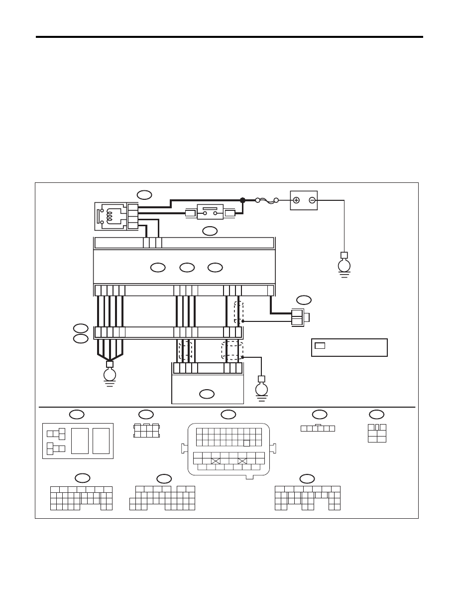
WIRING DIAGRAM:
EN-05673
5
6
7
8
2
1
9
4
3
10
24
22 23
25
11 12 13 14 15
26 27
28
16 17
18 19 20 21
33 34
29
32
30 31
1 2
7 8
3
4
5
6
1 2 3 4 5 6 7 8 9 10 11
12 13 14 15 16 17 18 19 20 21 22
23 24 25
34 35
36 37 38 39 40 41
48 49
50 51 52 53 54
42 43
44 45
46 47
26 27 28 29 30 31 32 33
1 2 3 4
5 6 7 8
1
2
7
8 9
5
6
3
4
10 11 12
19 20 21
29
30 31
13 14 15 16 17
27
28
18
22 23
24 25
26
1
2
8 9
5
6
3
4
10 11 12
19 20 21
29 30
31
13 14 15 16
17
27
28
18
22 23 24 25 26
7
32 33 34 35
1 2 3 4 5 6
E57
B47
B137
D:
B21
B122
B136
C:
B362
B134
A:
36
40
34
35
37
E2
B21
C21
C1
A29
6
A18
C6
A28
6
4
25
*
*
B122
24
E
38
39
28
D5
D4
A19
A5
D7
D1
D2
D3
3
E57
2
1
5
B134
B362
B47
5
7
6
A:
B137
B136
D:
C:
*
E
SBF-7
8
6
4
E
3
4
1
2
5
6
ELECTRONIC
THROTTLE
CONTROL RELAY
MAIN RELAY
BATTERY
ECM
ELECTRONIC THROTTLE
CONTROL
: TERMINAL No. OPTIONAL
ARRANGEMENT

EN(H4DOTC)(diag)-324
Diagnostic Procedure with Diagnostic Trouble Code (DTC)
ENGINE (DIAGNOSTICS)
Step
Check
Yes
No
1
CHECK ELECTRONIC THROTTLE CON-
TROL RELAY.
1) Turn the ignition switch to OFF.
2) Remove the electronic throttle control relay.
3) Connect the battery to terminals No. 5 and
No. 6 of electronic throttle control relay.
4) Measure the resistance between electronic
throttle control relay terminals.
Terminals
No. 7 — No. 8:
Is the resistance less than 1
:? Go to step 2.
Replace the elec-
tronic throttle con-
trol relay. <Ref. to
FU(H4DOTC)-55,
Electronic Throttle
Control Relay.>
2
CHECK POWER SUPPLY OF ELECTRONIC
THROTTLE CONTROL RELAY.
Measure the voltage between electronic throttle
control relay connector and chassis ground.
Connector & terminal
(B362) No. 7 (+) — Chassis ground (–):
Is the voltage 10 V or more?
Go to step 3.
Repair the open or
ground short circuit
of power supply
circuit.
3
CHECK HARNESS BETWEEN ECM AND
ELECTRONIC THROTTLE CONTROL RE-
LAY.
1) Disconnect the connectors from ECM.
2) Turn the ignition switch to ON.
3) Measure the voltage between electronic
throttle control relay connector and chassis
ground.
Connector & terminal
(B362) No. 6 (+) — Chassis ground (–):
Is the voltage 10 V or more?
Repair the short
circuit to power in
harness between
ECM and elec-
tronic throttle con-
trol relay.
Go to step 4.
4
CHECK HARNESS BETWEEN ECM AND
ELECTRONIC THROTTLE CONTROL RE-
LAY.
1) Turn the ignition switch to OFF.
2) Measure the resistance between electronic
throttle control relay connector and chassis
ground.
Connector & terminal
(B362) No. 6 — Chassis ground:
(B362) No. 8 — Chassis ground:
Is the resistance 1 M
: or
more?
Go to step 5.
Repair the ground
short circuit of har-
ness between
ECM and elec-
tronic throttle con-
trol relay.
5
CHECK HARNESS BETWEEN ECM AND
ELECTRONIC THROTTLE CONTROL RE-
LAY.
Measure the resistance between ECM and
electronic throttle control relay connector.
Connector & terminal
(B136) No. 21 — (B362) No. 6:
(B136) No. 1 — (B362) No. 8:
Is the resistance less than 1
:? Repair the poor
contact of ECM
connector.
Repair the open
circuit of harness
between ECM and
electronic throttle
control relay.
Нет комментариевНе стесняйтесь поделиться с нами вашим ценным мнением.
Текст