Subaru Legacy IV (2008 year). Service manual — part 32
FU(H4SO)-17
Intake Manifold
FUEL INJECTION (FUEL SYSTEMS)
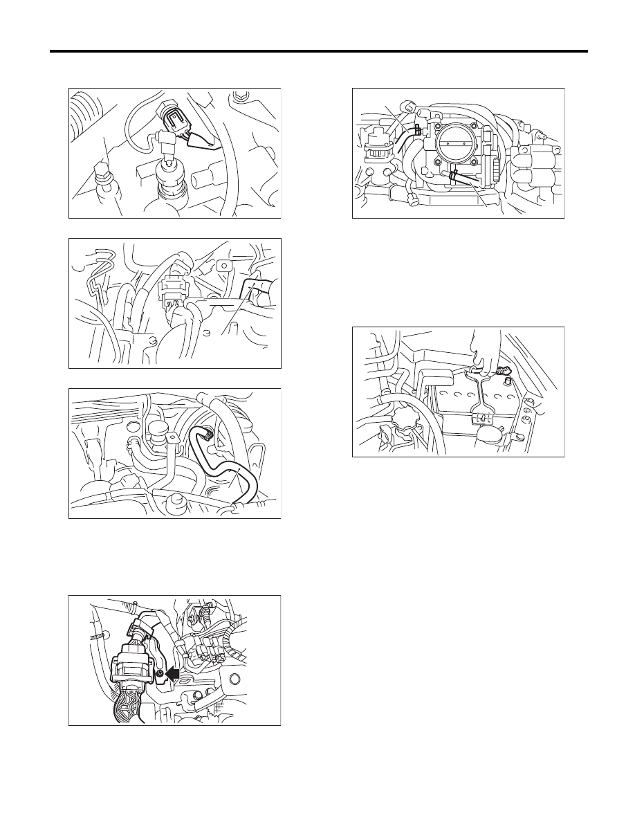
13) Connect the connector to engine coolant tem-
perature sensor.
14) Connect the PCV hose (A) to intake manifold.
15) Connect the brake booster hose (A).
16) Connect the engine harness connector to the
bulkhead harness connector and fasten to the rear
engine hanger with bolt.
Tightening torque:
6.4 N·m (0.7 kgf-m, 4.7 ft-lb)
17) Connect the engine coolant hoses (A) to throt-
tle body.
18) Connect the spark plug cords to spark plugs.
19) Install the generator. <Ref. to SC(H4SO)-14,
INSTALLATION, Generator.>
20) Install the air intake duct and air intake cham-
ber. <Ref. to IN(H4SO)-8, INSTALLATION, Air In-
take Duct.> <Ref. to IN(H4SO)-7, INSTALLATION,
Air Intake Chamber.>
21) Connect the ground cable to battery.
22) Lift up the vehicle.
23) Install the under cover.
24) Lower the vehicle.
25) Fill engine coolant. <Ref. to CO(H4SO)-13,
DRAINING OF ENGINE COOLANT, REPLACE-
MENT, Engine Coolant.>
FU-00055
(A)
FU-03956
FU-02320
(A)
FU-03924
FU-01085
(A)
(A)
IN-00203
FU(H4SO)-18
Intake Manifold
FUEL INJECTION (FUEL SYSTEMS)
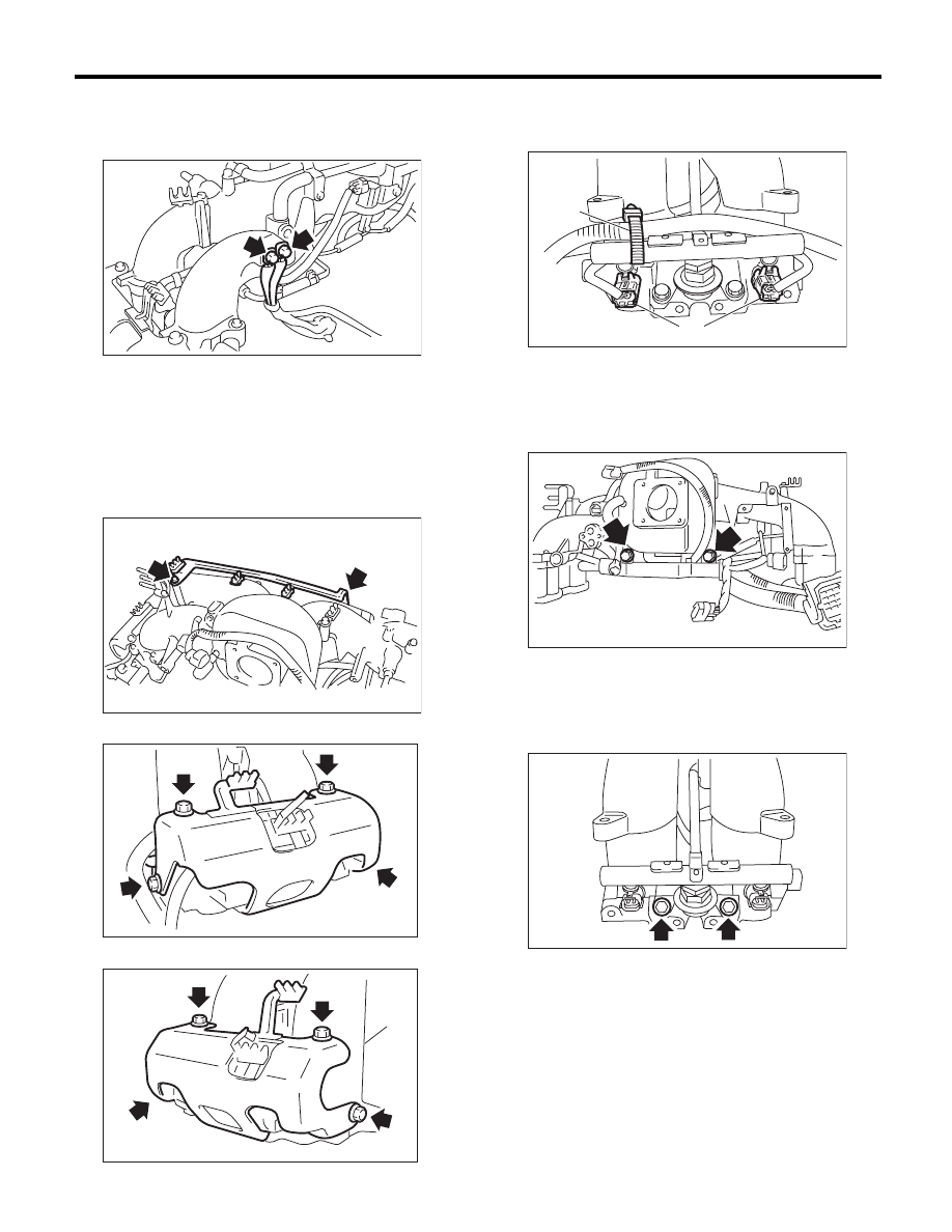
C: DISASSEMBLY
1) Disconnect the engine ground terminal from in-
take manifold.
2) Remove the ignition coil and ignitor assembly.
<Ref. to IG(H4SO)-6, REMOVAL, Ignition Coil and
Ignitor Assembly.>
3) Remove the throttle body. <Ref. to FU(H4SO)-
12, REMOVAL, Throttle Body.>
4) Remove the EGR valve. <Ref. to FU(H4SO)-29,
REMOVAL, EGR Valve.>
5) Remove the plug cord stay.
6) Remove the fuel pipe protector LH.
7) Remove the fuel pipe protector RH.
8) Disconnect the connectors (A) from fuel injector.
9) Remove the harness band (B) which holds the
engine harness to the fuel injector pipe.
10) Remove the purge control solenoid valve.
<Ref. to EC(H4SO)-7, REMOVAL, Purge Control
Solenoid Valve.>
11) Remove the bolts which hold engine harness to
intake manifold.
12) Remove the engine harness from intake mani-
fold.
13) Remove the bolts which install fuel injector pipe
on the intake manifold as shown in the figure
• RH side
FU-01090
FU-03233
FU-02325
FU-02326
(A)
(B)
FU-03955
FU-03450
FU-02717
FU(H4SO)-19
Intake Manifold
FUEL INJECTION (FUEL SYSTEMS)
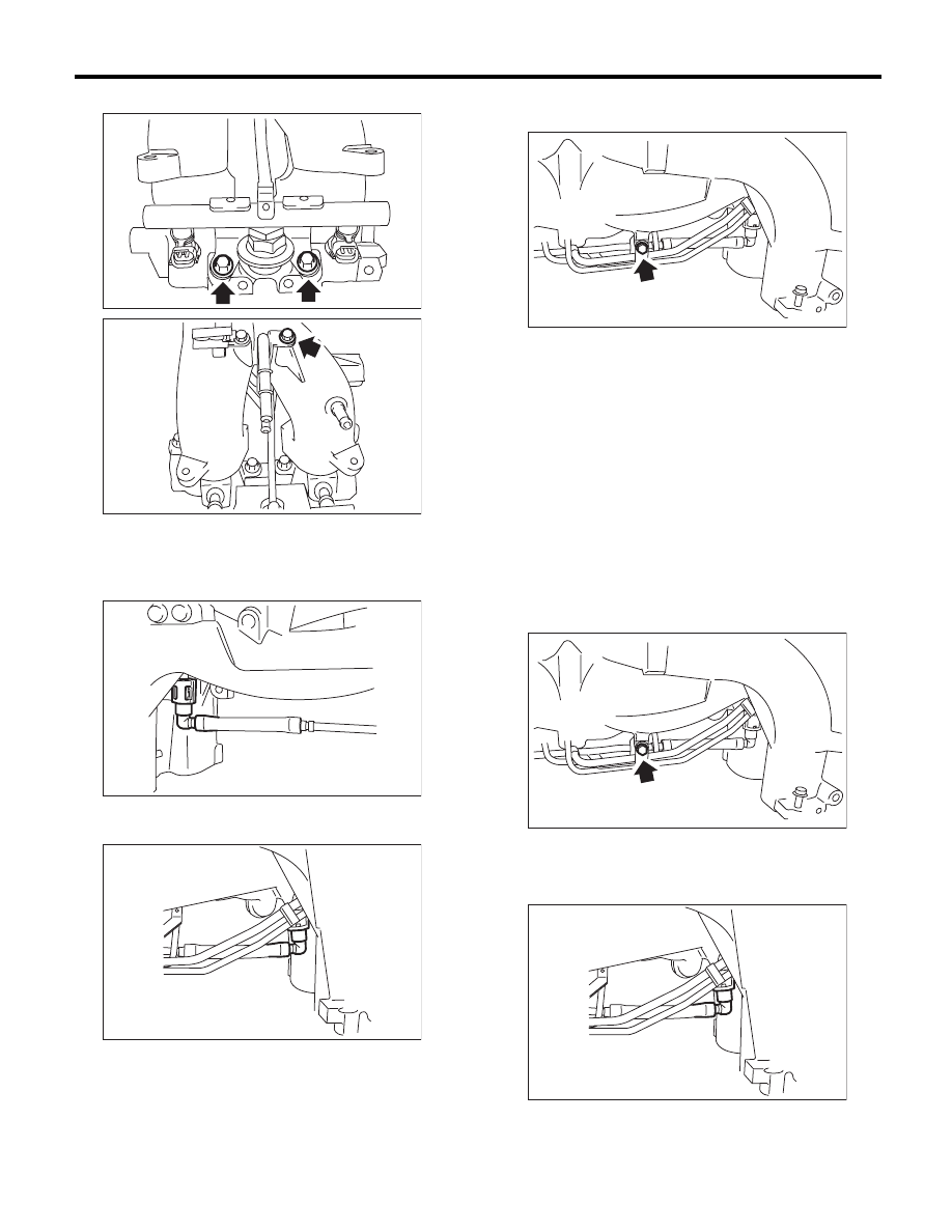
• LH side
14) Remove the fuel injectors from the fuel injector
pipe.
15) Disconnect the quick connector that fastens the
fuel injector pipe RH to the fuel pipe.
16) Disconnect the quick connector that fastens the
fuel injector pipe LH to the fuel pipe.
17) Remove the fuel injector pipe RH and LH.
18) Remove the bolts which install fuel pipes on in-
take manifold.
19) Remove the fuel pipe from the intake manifold.
D: ASSEMBLY
NOTE:
When assembling the nipple, apply liquid gasket.
Liquid gasket:
THREE BOND 1105 (Part No. 004403010) or
equivalent
Tightening torque:
17 N·m (1.7 kgf-m, 12.5 ft-lb)
1) Tighten the bolts which install fuel pipes on in-
take manifold.
Tightening torque:
6.4 N·m (0.7 kgf-m, 4.7 ft-lb)
2) Connect the fuel injector pipe LH to the fuel pipe.
NOTE:
Connect the quick connector securely.
FU-02718
FU-02719
FU-02720
FU-02721
FU-02722
FU-02722
FU-02721
FU(H4SO)-20
Intake Manifold
FUEL INJECTION (FUEL SYSTEMS)
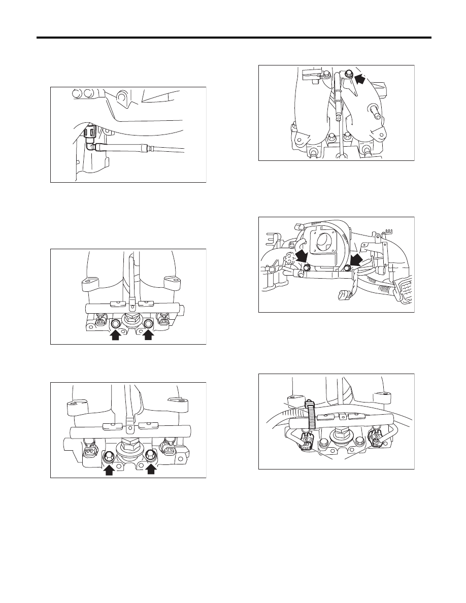
3) Connect the fuel injector pipe RH to the fuel
pipe.
NOTE:
Connect the quick connector securely.
4) Install the fuel injector.
5) Tighten the bolts which install fuel injector pipes
on intake manifold.
• RH side
Tightening torque:
19 N·m (1.9 kgf-m, 14.0 ft-lb)
• LH side
Tightening torque:
19 N·m (1.9 kgf-m, 14.0 ft-lb)
Tightening torque:
6.4 N·m (0.7 kgf-m, 4.7 ft-lb)
6) Install the engine harness to the intake manifold.
7) Tighten the bolts which install engine harness on
intake manifold.
Tightening torque:
19 N·m (1.9 kgf-m, 14.0 ft-lb)
8) Install the purge control solenoid valve. <Ref. to
EC(H4SO)-7, INSTALLATION, Purge Control So-
lenoid Valve.>
9) Connect the connectors (A) to fuel injector.
10) Hold the engine harness to injector pipe by har-
ness band (B).
FU-02720
FU-02717
FU-02718
FU-02719
FU-03450
(A)
(B)
FU-03955
Нет комментариевНе стесняйтесь поделиться с нами вашим ценным мнением.
Текст