Subaru Legacy IV (2008 year). Service manual — part 738
5AT-76
Reduction Driven Gear
AUTOMATIC TRANSMISSION
E: INSPECTION
Make sure the ball bearing and gear is not de-
formed or damaged.
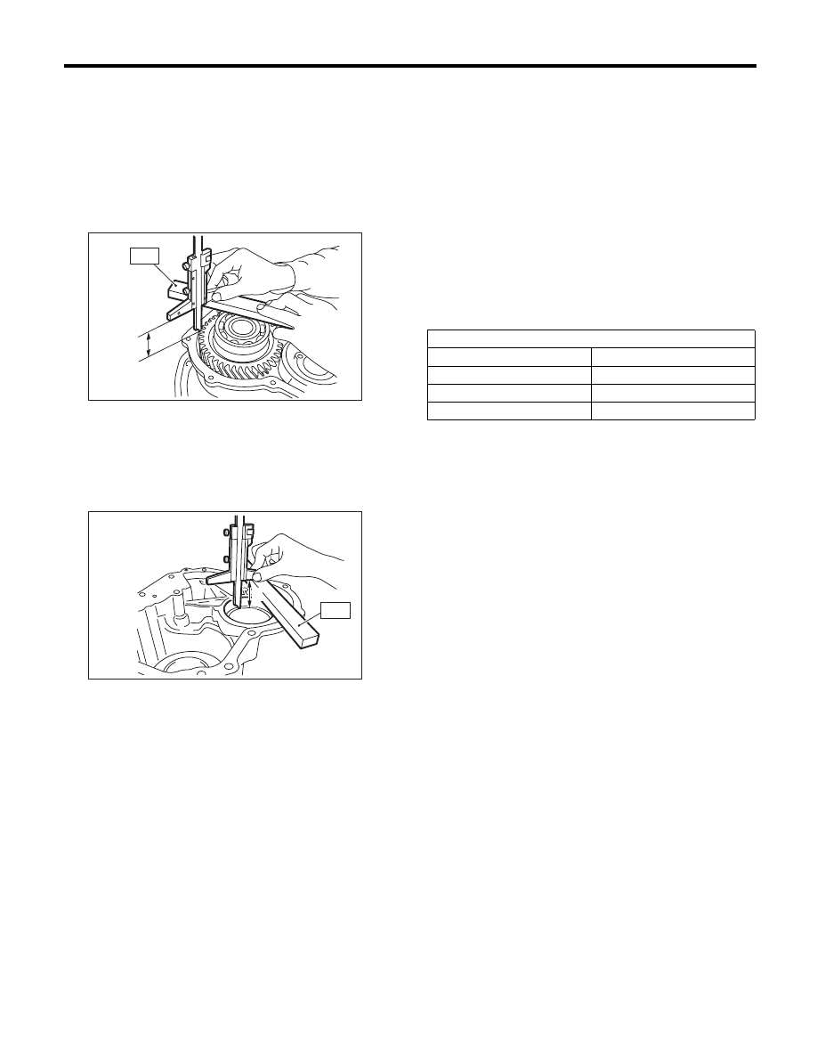
F: ADJUSTMENT
1) Using the ST, measure the height “A” from the
AT main case mating surface to ball bearing outer
ring contact surface.
ST
499575400
GAUGE
2) Using the ST, measure the depth “B”, which is
from mating surface of extension case to ball bear-
ing outer ring contact surface.
ST
499575400
GAUGE
3) Calculation formula:
Select the ball bearing shim from the table to adjust
clearances within 0.05 — 0.25 mm (0.0020 —
0.0098 in).
When clearances are 0.05 mm (0.0020 in):
T (mm) = B – A + 0.23
[T (in) = B – A + 0.0091]
When clearances are 0.25 mm (0.0098 in):
T (mm) = B – A + 0.03
[T (in) = B – A + 0.0012]
T: Shim clearance
A: Height from the mating surface of the AT main
case to the ball bearing outer ring end surface
B: Depth from mating surface of extension case to
ball bearing outer ring contact surface
A Measured value
B Measured value
AT-03269
ST
A
AT-03270
B
ST
Reduction gear shim
Part No.
Thickness mm (in)
31288AA030
0.2 (0.008)
31288AA050
0.5 (0.020)
31288AA060
0.3 (0.012)
5AT-77
Center Differential Carrier
AUTOMATIC TRANSMISSION
29.Center Differential Carrier
A: REMOVAL
1) Remove the transmission assembly from vehicle
body. <Ref. to 5AT-39, REMOVAL, Automatic
Transmission Assembly.>
2) Remove the rear vehicle speed sensor, and sep-
arate the extension case from transmission case.
<Ref. to 5AT-68, REMOVAL, Extension Case.>
3) Extract the rear drive shaft. <Ref. to 5AT-73, RE-
MOVAL, Rear Drive Shaft.>
4) Pull out the center differential carrier assembly.
5) Pull out the shim(s) from transmission case.
B: INSTALLATION
1) Install the center differential assembly with the
shim(s).
NOTE:
Press-fit it to the bottom of bearing shoulder com-
pletely.
2) Insert the rear drive shaft. <Ref. to 5AT-73, IN-
STALLATION, Rear Drive Shaft.>
3) Join the transmission case and the extension
case, and then install the rear vehicle speed sen-
sor. <Ref. to 5AT-68, INSTALLATION, Extension
Case.>
4) Install the transmission assembly to the vehicle.
<Ref. to 5AT-43, INSTALLATION, Automatic
Transmission Assembly.>
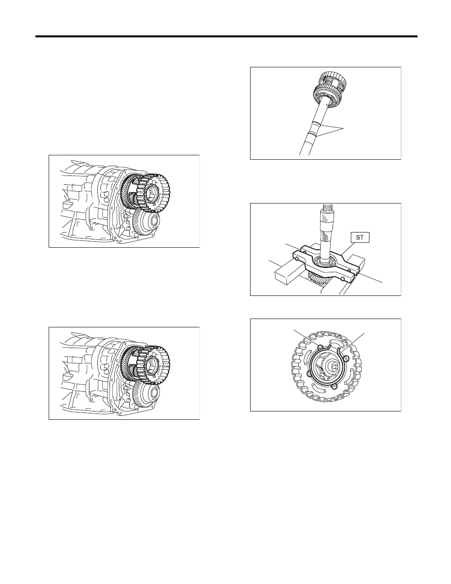
C: DISASSEMBLY
1) Remove the seal ring.
2) Using a press and ST, remove the ball bearing.
ST
498077600
REMOVER
3) Remove the snap ring, and pull out the shaft
from center differential assembly.
AT-01972
AT-01972
(A) Seal ring
(A) Snap ring
(B) Shaft
(A)
AT-02015
AT-00167
AT-01973
(A)
(B)
5AT-78
Center Differential Carrier
AUTOMATIC TRANSMISSION
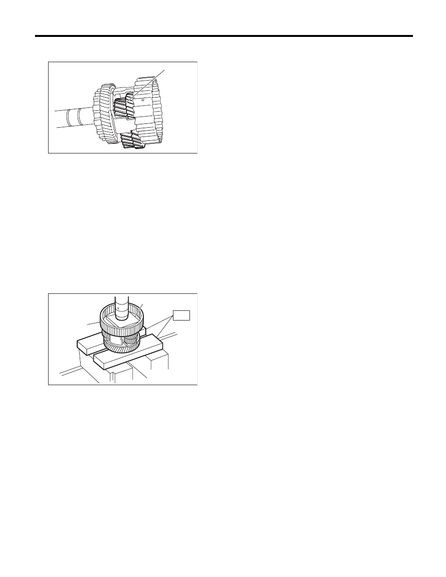
4) Remove the thrust washers, pinion gears and
washers from center differential assembly.
5) Pull out the intermediate shaft and thrust bear-
ing.
D: ASSEMBLY
1) Install the thrust washer onto intermediate shaft.
2) Install the thrust bearing onto intermediate shaft.
3) Install the pinion gears and washers.
4) Insert the shaft into the center differential as-
sembly.
5) Install the snap ring.
6) Using a press, install a new ball bearing into the
center differential assembly.
ST
498077000
REMOVER
7) Apply vaseline onto the seal ring outer surface
and shaft grooves.
8) Install a new seal ring.
E: INSPECTION
• Check each parts for holes, damages or other
foreign matters.
• Inspect the extension end play, and adjust it to
within the standard value. <Ref. to 5AT-70, AD-
JUSTMENT, Transfer Clutch.>
(A) Pinion gear
(A) Plate
(B) Center differential carrier
AT-00169
(A)
AT-00170
(A)
(B)
ST
5AT-79
Parking Pawl
AUTOMATIC TRANSMISSION
30.Parking Pawl
A: REMOVAL
1) Remove the transmission assembly from vehicle
body. <Ref. to 5AT-39, REMOVAL, Automatic
Transmission Assembly.>
2) Remove the extension case. <Ref. to 5AT-68,
REMOVAL, Extension Case.>
3) Remove the center differential carrier. <Ref. to
5AT-77, REMOVAL, Center Differential Carrier.>
4) Remove the front vehicle speed sensor. <Ref. to
5AT-52, REMOVAL, Front Vehicle Speed Sensor.>
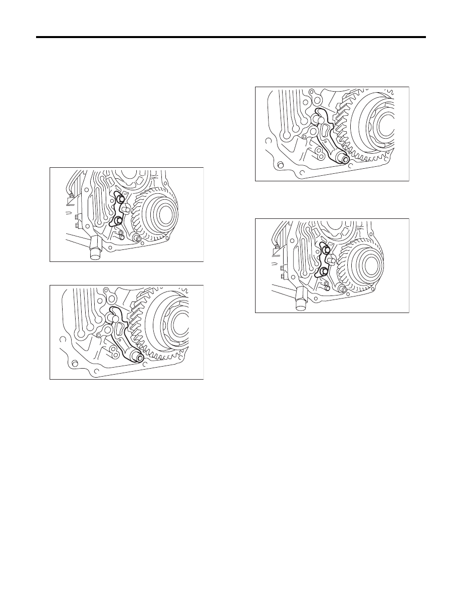
5) Remove the parking support actuator.
6) Remove the parking pawl, parking pawl shaft
and return spring.
B: INSTALLATION
1) Set the transmission to the “N” range.
2) Install the parking pawl, parking pawl shaft and
return spring.
3) Install the parking support actuator.
Tightening torque:
10
r
2 N·m (1.0
r
0.2 kgf-m, 7.4
r
1.5 ft-lb)
AT-03236
AT-03272
AT-03272
AT-03236
Нет комментариевНе стесняйтесь поделиться с нами вашим ценным мнением.
Текст