Subaru Legacy IV (2008 year). Service manual — part 457
FU(H6DO)-47
Fuel Tank
FUEL INJECTION (FUEL SYSTEMS)
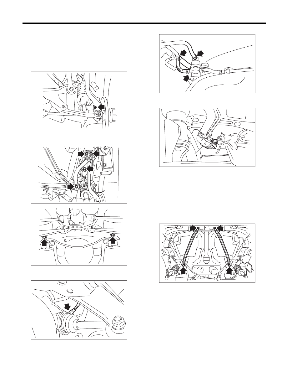
27) Remove the rear suspension assembly.
CAUTION:
A helper is required to perform this work.
(1) Support the rear suspension assembly with
the transmission jack.
(2) Remove the bolts which hold the rear shock
absorber to the rear suspension arm.
(3) Remove the bolts which secure the rear
suspension assembly to the body.
(4) Remove the rear suspension assembly.
28) Disconnect the connector.
29) Disconnect the evaporation hose.
30) Disconnect the fuel filler hose (A) and evapora-
tion hose (B).
31) Support the fuel tank with a transmission jack,
remove the bolts from the fuel tank band, and re-
move the fuel tank from the vehicle.
WARNING:
• A helper is required to perform this work.
• Fuel may remain in the fuel tank. This will
cause the left and right sides to be unbalanced.
Be careful not to drop the fuel tank when re-
moving.
FU-01132
FU-01133
FU-02891
FU-02392
FU-02393
(A)
FU-02394
(B)
FU-03293
FU(H6DO)-48
Fuel Tank
FUEL INJECTION (FUEL SYSTEMS)
B: INSTALLATION
1) Support the fuel tank with a transmission jack,
set the fuel tank in place, and temporarily tighten
the bolts of the fuel tank band.
WARNING:
A helper is required to perform this work.
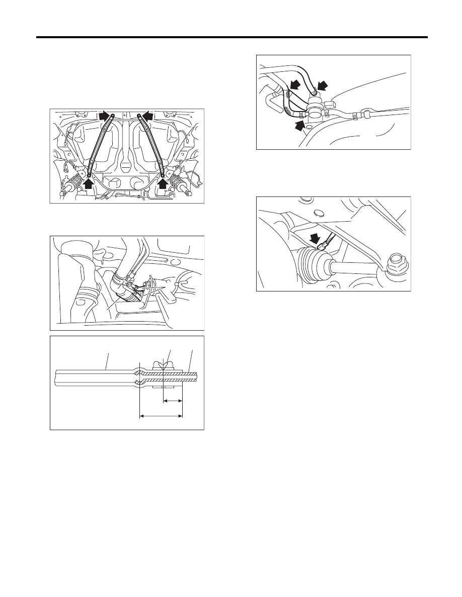
2) Securely insert the fuel filler hose (A) and evap-
oration hose (B) to the specified position, then tight-
en the clip or clamp.
3) Connect the evaporation hose.
4) Tighten the fuel tank band bolts.
Tightening torque:
33 N·m (3.4 kgf-m, 24.3 ft-lb)
5) Connect the connector.
(1) Hose
(2) Clip or clamp
(3) Pipe
FU-03293
(A)
FU-02394
(B)
( 1 )
( 2 )
( 3 )
FU-00104
L
L/2
FU-02393
FU-02392
FU(H6DO)-49
Fuel Tank
FUEL INJECTION (FUEL SYSTEMS)
6) Install the rear suspension assembly.
CAUTION:
A helper is required to perform this work.
(1) Support the rear suspension assembly with
a transmission jack.
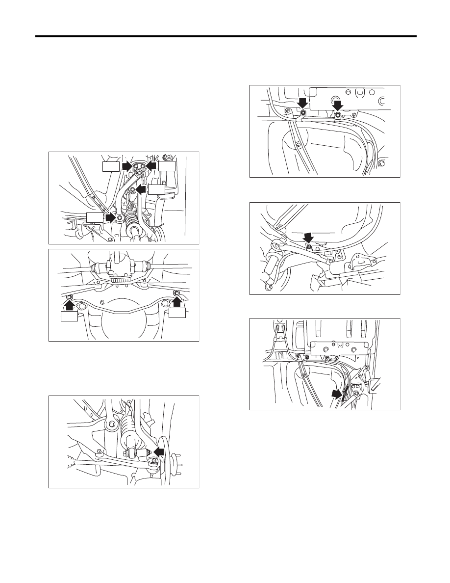
(2) Support the rear suspension assembly, and
tighten the bolts which secure the rear suspen-
sion assembly to the body.
Tightening torque:
T1: 125 N·m (12.7 kgf-m, 92.2 ft-lb)
T2: 175 N·m (17.8 kgf-m, 129.1 ft-lb)
(3) Tighten the bolts which hold the rear shock
absorber to the rear suspension arm. <Ref. to
RS-10, INSTALLATION, Rear Arm.>
Tightening torque:
62 N·m (6.3 kgf-m, 45.7 ft-lb)
7) Tighten the bolts holding the parking brake cable
clamp.
Tightening torque:
18 N·m (1.8 kgf-m, 13.3 ft-lb)
Tightening torque:
33 N·m (3.4 kgf-m, 24.3 ft-lb)
8) Connect the connector to the rear ABS wheel
speed sensor.
9) Install the heat shield cover.
Tightening torque:
17.5 N·m (1.8 kgf-m, 12.9 ft-lb)
10) Install the fuel tank protector.
Tightening torque:
Nut: 9 N·m (0.9 kgf-m, 6.6 ft-lb)
Bolt: 17.5 N·m (1.8 kgf-m, 12.9 ft-lb)
11) Install the propeller shaft. <Ref. to DS-11, IN-
STALLATION, Propeller Shaft.>
12) Install the rear exhaust pipe. <Ref. to
EX(H6DO)-8, INSTALLATION, Rear Exhaust
Pipe.>
13) Lower the vehicle.
FU-01150
T1
T1
T1
T1
FU-02892
T2
T2
FU-01132
FU-02895
FU-02896
FU-02894
FU(H6DO)-50
Fuel Tank
FUEL INJECTION (FUEL SYSTEMS)
14) Connect the parking brake cable to the parking
brake assembly. <Ref. to PB-7, INSTALLATION,
Parking Brake Assembly (Rear Disc Brake).>
15) Install the rear disc brake assembly.
Tightening torque:
66 N·m (6.7 kgf-m, 48.7 ft-lb)
16) Tighten the bolts which secure the rear brake
hose mounting bracket.
Tightening torque:
33 N·m (3.4 kgf-m, 24.3 ft-lb)
17) Install the rear wheels.
Tightening torque:
120 N·m (12.2 kgf-m, 88.5 ft-lb)
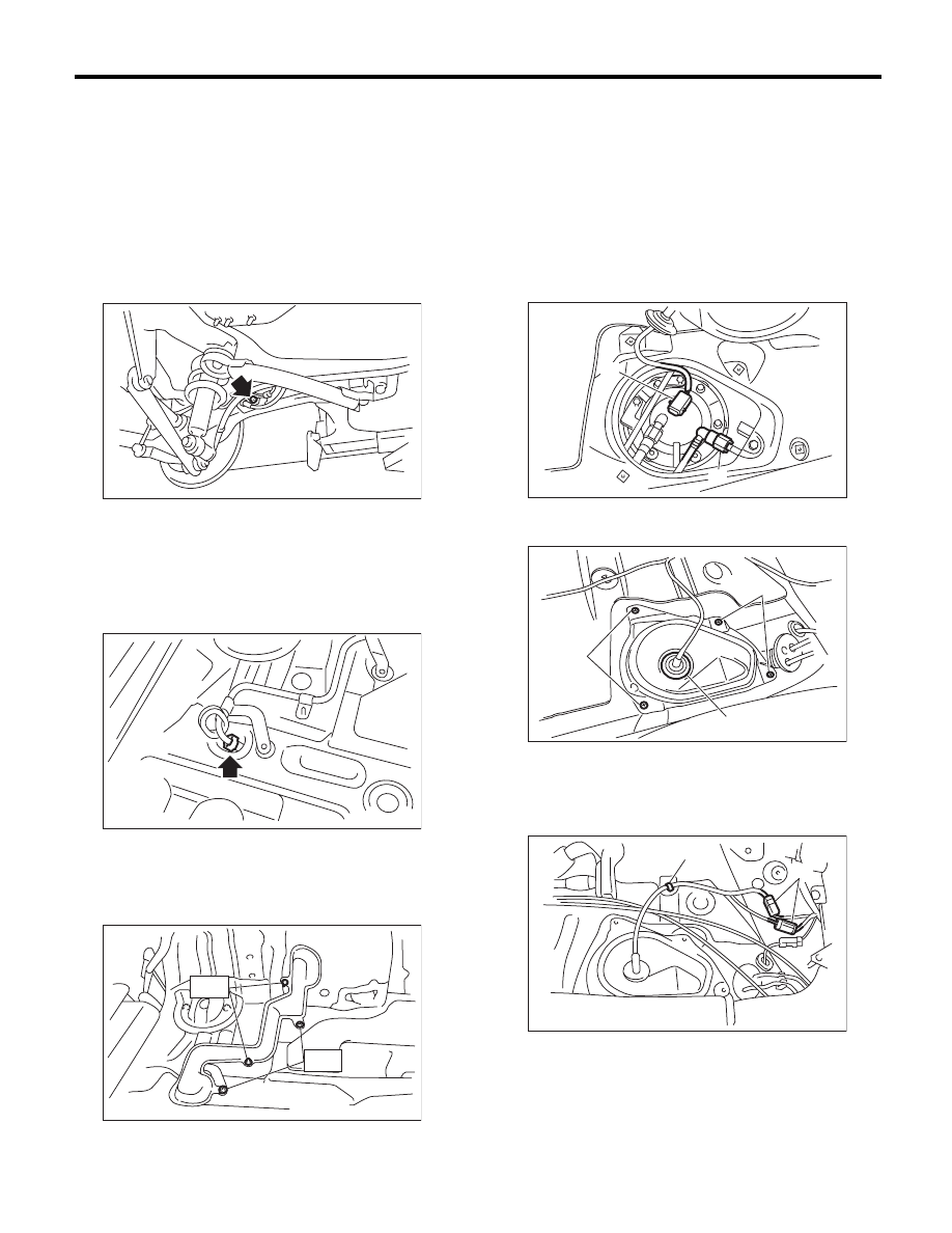
18) Connect the quick connector of the evaporation
pipe. <Ref. to FU(H6DO)-66, INSTALLATION, Fuel
Delivery and Evaporation Lines.>
19) Install the pipe protector.
Tightening torque:
T1: 1 N·m (0.1 kgf-m, 0.7 ft-lb)
T2: 7.5 N·m (0.8 kgf-m, 5.5 ft-lb)
20) Install the trunk room trim. (Sedan model)
<Ref. to EI-71, INSTALLATION, Trunk Room
Trim.>
21) Install the rear quarter trim. (Wagon model)
<Ref. to EI-64, INSTALLATION, Rear Quarter
Trim.>
22) Connect connector (A) to the fuel sub level sen-
sor.
23) Connect the quick connector of the fuel delivery
hose (B). <Ref. to FU(H6DO)-66, INSTALLATION,
Fuel Delivery and Evaporation Lines.>
24) Install the service hole cover of fuel sub level
sensor.
25) Connect connector (A) and install clip (B).
FU-01128
FU-02391
FU-02868
T2
T1
(A) Bolt
(B) Grommet
FU-02853
(A)
(B)
FU-03223
(B)
(A)
(A)
FU-03222
(B)
(A)
Нет комментариевНе стесняйтесь поделиться с нами вашим ценным мнением.
Текст