Subaru Legacy IV (2008 year). Service manual — part 458
FU(H6DO)-51
Fuel Tank
FUEL INJECTION (FUEL SYSTEMS)
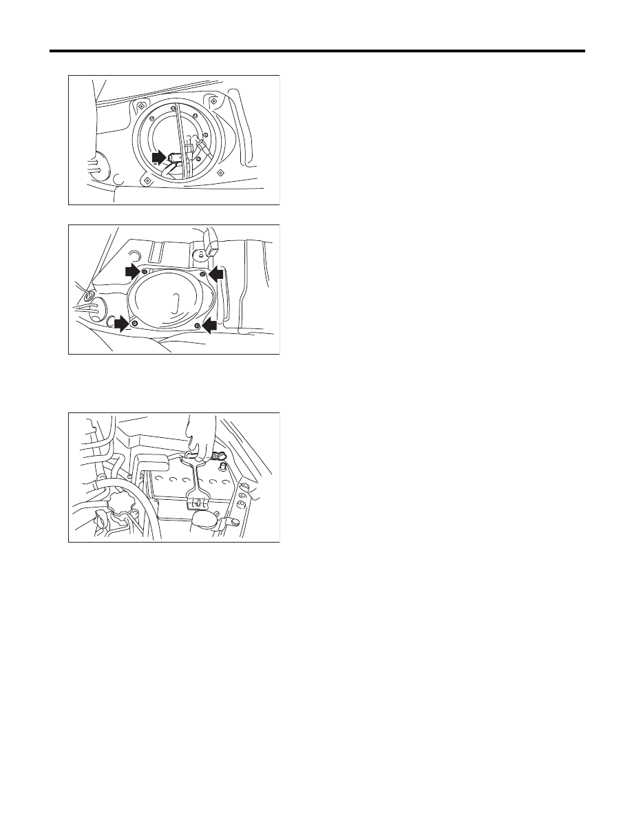
26) Connect the connector to the fuel pump.
27) Install the service hole cover of fuel pump.
28) Install the rear seat.
29) Install the fuse of fuel pump to the main fuse
box.
30) Connect the ground cable to battery.
31) Inspect the wheel alignment and adjust if nec-
essary.
C: INSPECTION
1) Check that the fuel tank does not have holes,
cracks or is damaged in any way.
2) Make sure that the fuel pipe and fuel hose are
not cracked and that the connections are tight.
FU-03221
FU-02387
IN-00203
FU(H6DO)-52
Fuel Filler Pipe
FUEL INJECTION (FUEL SYSTEMS)
26.Fuel Filler Pipe
A: REMOVAL
WARNING:
Place “NO OPEN FLAMES” signs near the
working area.
CAUTION:
Be careful not to spill fuel.
1) Set the vehicle on a lift.
2) Release the fuel pressure. <Ref. to FU(H6DO)-
43, RELEASING OF FUEL PRESSURE, PROCE-
DURE, Fuel.>
3) Drain fuel. <Ref. to FU(H6DO)-43, DRAINING
FUEL (WITH SUBARU SELECT MONITOR),
PROCEDURE, Fuel.>
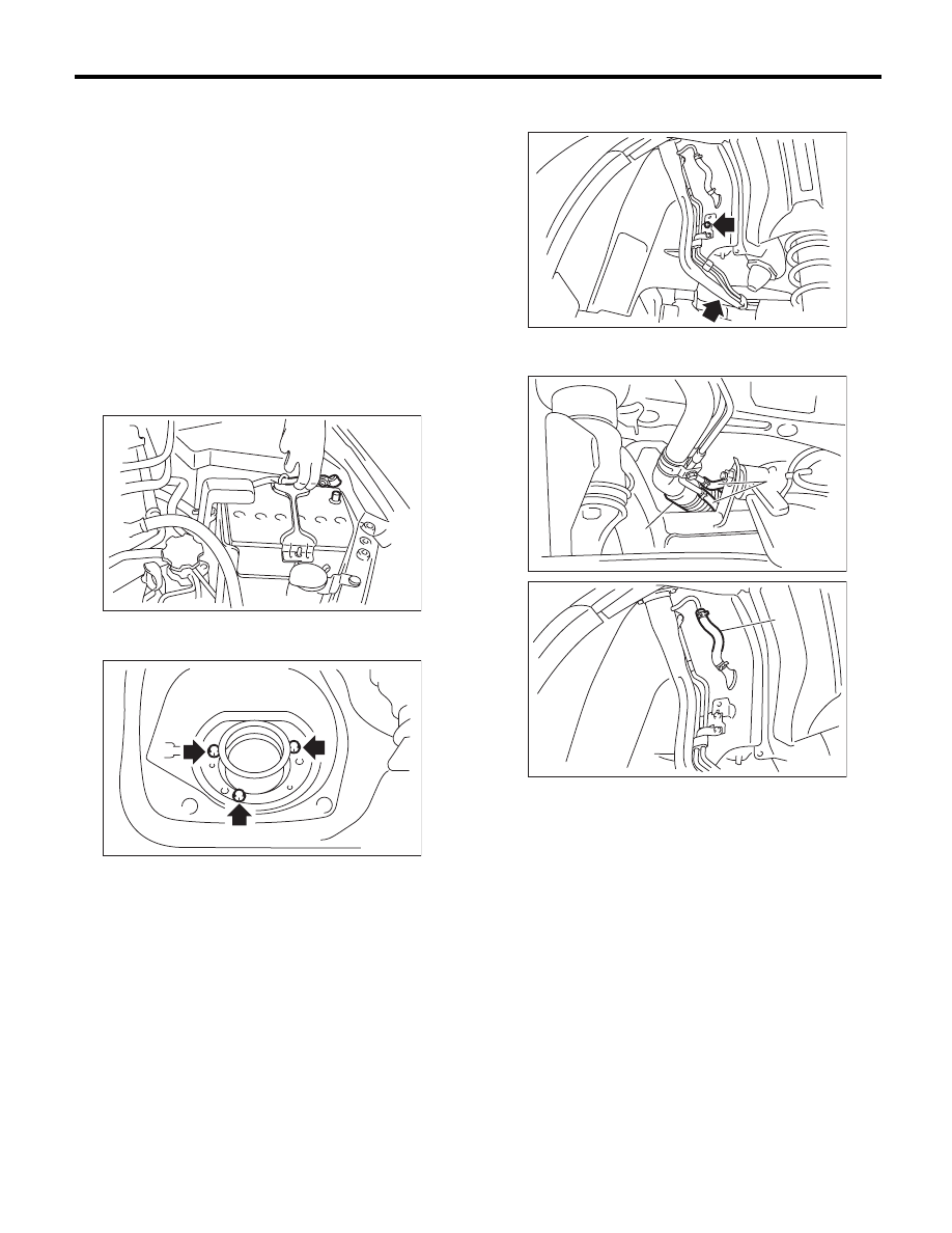
4) Disconnect the ground cable from battery.
5) Open the fuel filler lid, and remove the filler cap.
6) Remove the screws which secure gasket.
7) Remove the rear wheel RH.
8) Lift up the vehicle.
9) Remove the mud guard. <Ref. to EI-29, RE-
MOVAL, Mud Guard.>
10) Remove the rear sub frame. <Ref. to RS-21,
REMOVAL, Rear Sub Frame.>
11) Remove the bolts which hold fuel filler pipe
bracket on the body.
12) Disconnect the fuel filler hose (A) and evapora-
tion hose (B).
13) Remove the fuel filler pipe to the underside of
the vehicle.
IN-00203
FU-00095
FU-02395
(A)
FU-02396
(B)
FU-02397
(B)
FU(H6DO)-53
Fuel Filler Pipe
FUEL INJECTION (FUEL SYSTEMS)
B: INSTALLATION
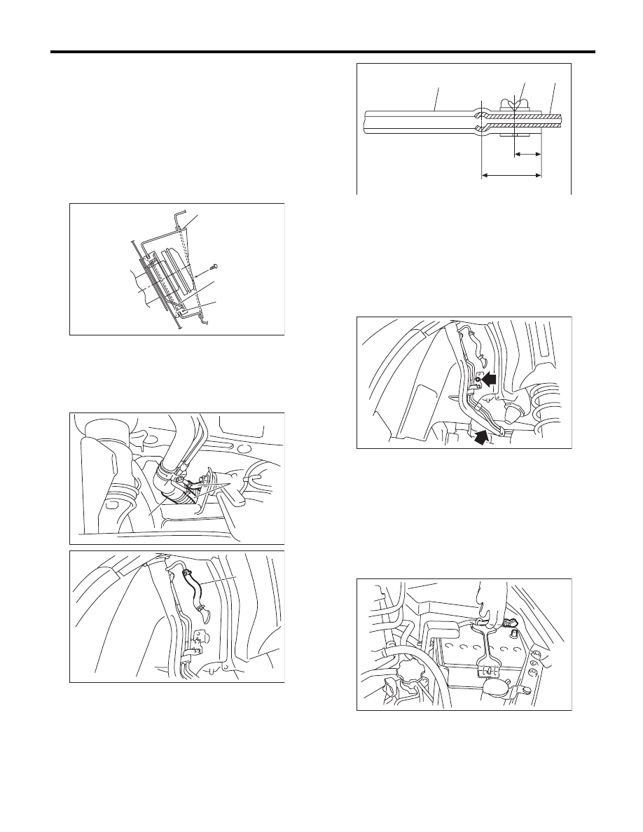
1) Open the fuel filler lid.
2) Set the fuel saucer (A) with rubber gasket (C),
and insert the fuel filler pipe into hole from the inner
side of apron.
3) Align the holes in fuel filler pipe neck and set the
cup (B), and tighten the screws.
NOTE:
If the edges of rubber gasket are folded toward in-
side, straighten it with a flat tip screwdriver.
4) Securely insert the fuel filler hose (A) and evap-
oration hose (B) into the specified position, then
tighten the clamp or clip as shown in the figure.
Tightening torque:
2.5 N·m (0.3 kgf-m, 1.8 ft-lb)
5) Tighten the bolts which hold fuel filler pipe brack-
et on the body.
Tightening torque:
7.5 N·m (0.8 kgf-m, 5.5 ft-lb)
6) Install the rear sub frame. <Ref. to RS-21, IN-
STALLATION, Rear Sub Frame.>
7) Install the mud guard. <Ref. to EI-29, INSTAL-
LATION, Mud Guard.>
8) Lower the vehicle.
9) Install the rear wheel RH.
Tightening torque:
120 N·m (12.2 kgf-m, 88.5 ft-lb)
10) Connect the ground cable to battery.
11) Inspect the wheel alignment and adjust if nec-
essary.
FU-00103
(A)
(C)
(B)
(A)
FU-02396
(B)
FU-02397
(B)
(1) Hose
(2) Clip or clamp
(3) Pipe
( 1 )
( 2 )
( 3 )
FU-00104
L
L/2
FU-02395
IN-00203
FU(H6DO)-54
Fuel Filler Pipe
FUEL INJECTION (FUEL SYSTEMS)
C: INSPECTION
1) Check that the fuel tank does not have holes,
cracks or is damaged in any way.
2) Make sure that the fuel hose is not cracked and
that the connections are tight.
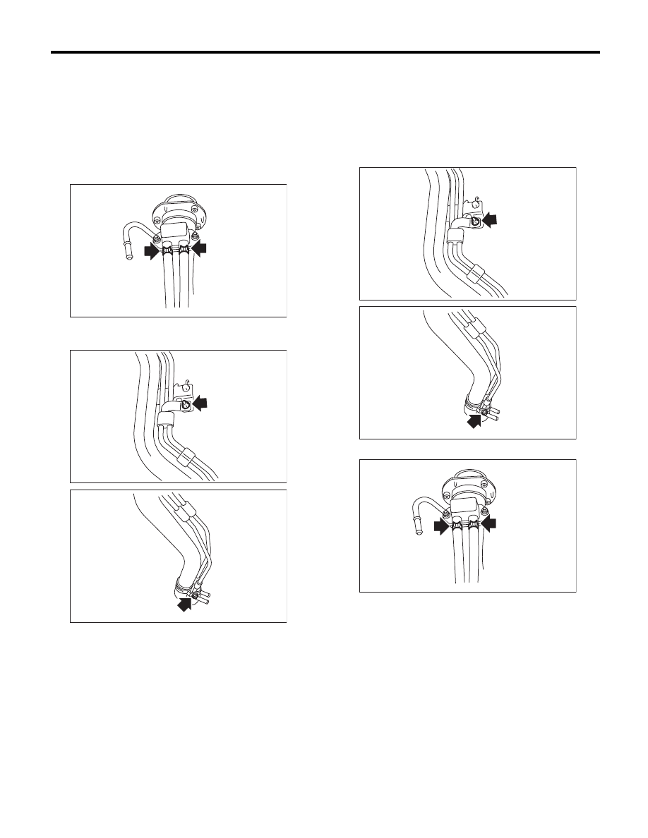
D: DISASSEMBLY
1) Move the clip and disconnect the evaporation
hose from the shut valve.
2) Remove the nut which holds the evaporation
pipe assembly to the fuel filler pipe.
3) Remove the shut valve from the fuel filler pipe.
<Ref. to EC(H4SO)-15, REMOVAL, Shut Valve.>
E: ASSEMBLY
1) Install the shut valve to the fuel filler pipe. <Ref.
to EC(H4SO)-15, INSTALLATION, Shut Valve.>
2) Tighten the nuts which secure the evaporation
pipe assembly to the fuel filler pipe.
Tightening torque:
7.5 N·m (0.8 kgf-m, 5.5 ft-lb)
3) Connect the evaporation hose to the shut valve.
FU-02398
FU-02399
FU-02400
FU-02399
FU-02400
FU-02398
Нет комментариевНе стесняйтесь поделиться с нами вашим ценным мнением.
Текст