Subaru Legacy IV (2008 year). Service manual — part 538
EN(H6DO)(diag)-125
Diagnostic Procedure with Diagnostic Trouble Code (DTC)
ENGINE (DIAGNOSTICS)
U: DTC P0083 INTAKE VALVE CONTROL SOLENOID CIRCUIT HIGH (BANK 2)
DTC DETECTING CONDITION:
• Immediately at fault recognition
• GENERAL DESCRIPTION <Ref. to GD(H6DO)-30, DTC P0083 INTAKE VALVE CONTROL SOLENOID
CIRCUIT HIGH (BANK 2), Diagnostic Trouble Code (DTC) Detecting Criteria.>
TROUBLE SYMPTOM:
Improper idling
CAUTION:
After repair or replacement of faulty parts, perform Clear Memory Mode <Ref. to EN(H6DO)(diag)-52,
OPERATION, Clear Memory Mode.>, and Inspection Mode <Ref. to EN(H6DO)(diag)-44, PROCEDURE,
Inspection Mode.>.
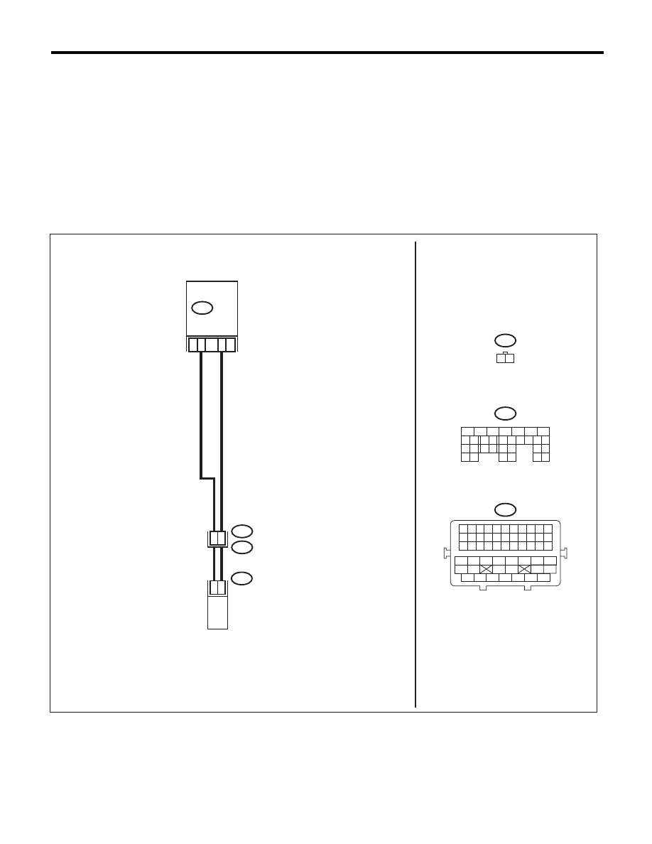
WIRING DIAGRAM:
EN-06871
E70
1 2
B137
5
6
7
8
2
1
9
4
3
10
22 23
11 12 13 14 15
24 25
26
16 17
18 19 20 21
27
28 29
30 31
B21
1 2 3 4 5 6 7 8 9 10 11
12 13 14 15 16 17 18 19 20 21 22
23 24 25 26 27 28 29 30 31 32 33
34
35
42
43
36
37
38
39
48
49
50
51
52
53
54
40
41
44
45
46
47
B21
E2
B137
E70
30
2
1
30
29
31
ECM
OIL SWITCHING
SOLENOID VALVE LH

EN(H6DO)(diag)-126
Diagnostic Procedure with Diagnostic Trouble Code (DTC)
ENGINE (DIAGNOSTICS)
Step
Check
Yes
No
1
CHECK HARNESS BETWEEN ECM AND OIL
SWITCHING SOLENOID VALVE.
1) Turn the ignition switch to OFF.
2) Disconnect the connectors from the ECM
and oil switching solenoid valve.
3) Measure the voltage between ECM and
chassis ground.
Connector & terminal
(B137) No. 31 (+) — Chassis ground (–):
(B137) No. 30 (+) — Chassis ground (–):
Is the voltage less than 1 V?
Go to step 2.
Repair the short
circuit of harness
to power supply
between ECM and
oil switching sole-
noid valve connec-
tor.
2
CHECK HARNESS BETWEEN ECM AND OIL
SWITCHING SOLENOID VALVE.
Measure the resistance between ECM and oil
switching solenoid valve connector.
Connector & terminal
(B137) No. 31 — (E70) No. 1:
(B137) No. 30 — (E70) No. 2:
Is the resistance less than 1
:? Go to step 3.
Repair the harness
and connector.
NOTE:
In this case, repair
the following item:
• Open circuit of
harness between
ECM and oil
switching solenoid
valve connector
• Poor contact of
coupling connector
3
CHECK OIL SWITCHING SOLENOID VALVE.
Measure the resistance between oil switching
solenoid valve terminals.
Terminals
No. 1 — No. 2:
Is the resistance between 6 —
12
:?
Repair the poor
contact of ECM
and oil switching
solenoid valve con-
nector.
Replace the oil
switching solenoid
valve. <Ref. to
ME(H6DO)-80, Oil
Switching Solenoid
Valve.>
EN(H6DO)(diag)-127
Diagnostic Procedure with Diagnostic Trouble Code (DTC)
ENGINE (DIAGNOSTICS)
V: DTC P0101 MASS OR VOLUME AIR FLOW CIRCUIT RANGE/PERFORMANCE
DTC DETECTING CONDITION:
• Two consecutive driving cycles with fault
• GENERAL DESCRIPTION <Ref. to GD(H6DO)-31, DTC P0101 MASS OR VOLUME AIR FLOW CIRCUIT
RANGE/PERFORMANCE, Diagnostic Trouble Code (DTC) Detecting Criteria.>
TROUBLE SYMPTOM:
• Improper idling
• Engine stalls.
• Poor driving performance
CAUTION:
After repair or replacement of faulty parts, perform Clear Memory Mode <Ref. to EN(H6DO)(diag)-52,
OPERATION, Clear Memory Mode.>, and Inspection Mode <Ref. to EN(H6DO)(diag)-44, PROCEDURE,
Inspection Mode.>.
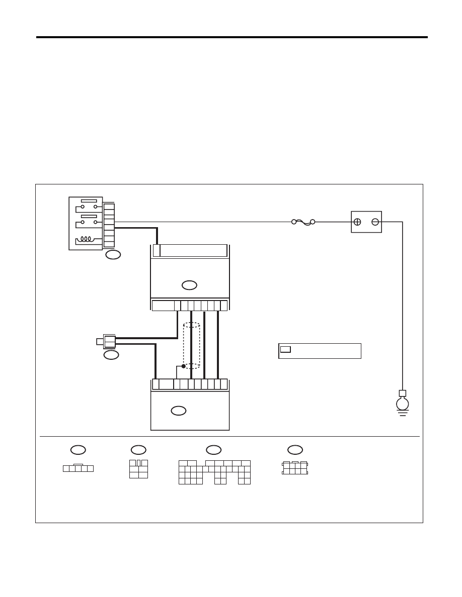
WIRING DIAGRAM:
EN-03920
B83
B3
BATTERY
E
B83
1
B3
MASS AIR FLOW & INTAKE
AIR TEMPERATURE SENSOR
ECM
B135
SBF-7
1 2 3 4 5
3
4
1
2
5
6
B135
B47
*
*
2
4
3
5
34
18
26
30
35
MAIN RELAY
B47
1
2
4
6
3
5
1 2 3 4
5 6 7 8
*
: TERMINAL No.
OPTIONAL ARRANGEMENT
5
6
7
8
2
1
9
4
3
10
24
22 23
25
11 12 13 14 15
26 27
28
16 17 18 19
20 21
29 30 31
32 33
34 35

EN(H6DO)(diag)-128
Diagnostic Procedure with Diagnostic Trouble Code (DTC)
ENGINE (DIAGNOSTICS)
Step
Check
Yes
No
1
CHECK FOR ANY OTHER DTC ON DISPLAY. Is any other DTC displayed?
Check the appro-
priate DTC using
the “List of Diag-
nostic Trouble
Code (DTC)”.
<Ref. to
EN(H6DO)(diag)-
81, List of Diagnos-
tic Trouble Code
(DTC).>
Replace the mass
air flow and intake
air temperature
sensor. <Ref. to
FU(H6DO)-26,
Mass Air Flow and
Intake Air Temper-
ature Sensor.>
Нет комментариевНе стесняйтесь поделиться с нами вашим ценным мнением.
Текст