Subaru Legacy IV (2008 year). Service manual — part 537

EN(H6DO)(diag)-121
Diagnostic Procedure with Diagnostic Trouble Code (DTC)
ENGINE (DIAGNOSTICS)
S: DTC P0077 INTAKE VALVE CONTROL SOLENOID CIRCUIT HIGH (BANK 1)
DTC DETECTING CONDITION:
• Immediately at fault recognition
• GENERAL DESCRIPTION <Ref. to GD(H6DO)-30, DTC P0077 INTAKE VALVE CONTROL SOLENOID
CIRCUIT HIGH (BANK 1), Diagnostic Trouble Code (DTC) Detecting Criteria.>
TROUBLE SYMPTOM:
Improper idling
CAUTION:
After repair or replacement of faulty parts, perform Clear Memory Mode <Ref. to EN(H6DO)(diag)-52,
OPERATION, Clear Memory Mode.>, and Inspection Mode <Ref. to EN(H6DO)(diag)-44, PROCEDURE,
Inspection Mode.>.
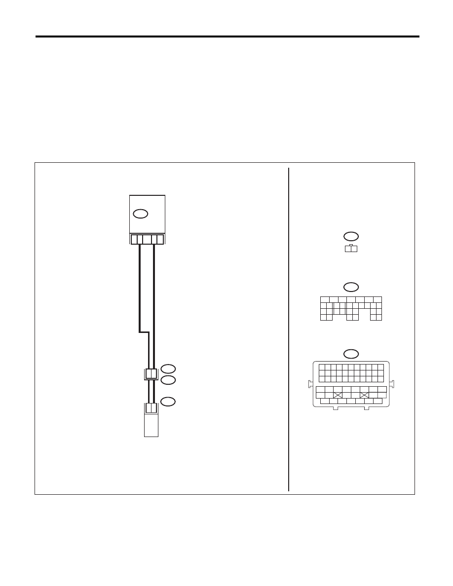
WIRING DIAGRAM:
EN-06870
B21
E2
B137
E69
24
2
1
26
25
E69
1 2
25
ECM
OIL SWITCHING
SOLENOID VALVE RH
B137
5
6
7
8
2
1
9
4
3
10
22 23
11 12 13 14 15
24 25
26
16 17
18 19 20 21
27
28 29
30 31
B21
1 2 3 4 5 6 7 8 9 10 11
12 13 14 15 16 17 18 19 20 21 22
23 24 25 26 27 28 29 30 31 32 33
34
35
42
43
36
37
38
39
48
49
50
51
52
53
54
40
41
44
45
46
47

EN(H6DO)(diag)-122
Diagnostic Procedure with Diagnostic Trouble Code (DTC)
ENGINE (DIAGNOSTICS)
Step
Check
Yes
No
1
CHECK HARNESS BETWEEN ECM AND OIL
SWITCHING SOLENOID VALVE.
1) Turn the ignition switch to OFF.
2) Disconnect the connectors from the ECM
and oil switching solenoid valve.
3) Measure the voltage between ECM and
chassis ground.
Connector & terminal
(B137) No. 25 (+) — Chassis ground (–):
(B137) No. 24 (+) — Chassis ground (–):
Is the voltage less than 1 V?
Go to step 2.
Repair the short
circuit of harness
to power supply
between ECM and
oil switching sole-
noid valve connec-
tor.
2
CHECK HARNESS BETWEEN ECM AND OIL
SWITCHING SOLENOID VALVE.
Measure the resistance of harness between
ECM and oil switching solenoid valve connec-
tor.
Connector & terminal
(B137) No. 25 — (E69) No. 1:
(B137) No. 24 — (E69) No. 2:
Is the resistance less than 1
:? Go to step 3.
Repair the harness
and connector.
NOTE:
In this case, repair
the following item:
• Open circuit of
harness between
ECM and oil
switching solenoid
valve connector
• Poor contact of
coupling connector
3
CHECK OIL SWITCHING SOLENOID VALVE.
Measure the resistance between oil switching
solenoid valve terminals.
Terminals
No. 1 — No. 2:
Is the resistance between 6 —
12
:?
Repair the poor
contact of ECM
and oil switching
solenoid valve con-
nector.
Replace the oil
switching solenoid
valve. <Ref. to
ME(H6DO)-80, Oil
Switching Solenoid
Valve.>
EN(H6DO)(diag)-123
Diagnostic Procedure with Diagnostic Trouble Code (DTC)
ENGINE (DIAGNOSTICS)
T: DTC P0082 INTAKE VALVE CONTROL SOLENOID CIRCUIT LOW (BANK 2)
DTC DETECTING CONDITION:
• Immediately at fault recognition
• GENERAL DESCRIPTION <Ref. to GD(H6DO)-30, DTC P0082 INTAKE VALVE CONTROL SOLENOID
CIRCUIT LOW (BANK 2), Diagnostic Trouble Code (DTC) Detecting Criteria.>
TROUBLE SYMPTOM:
Improper idling
CAUTION:
After repair or replacement of faulty parts, perform Clear Memory Mode <Ref. to EN(H6DO)(diag)-52,
OPERATION, Clear Memory Mode.>, and Inspection Mode <Ref. to EN(H6DO)(diag)-44, PROCEDURE,
Inspection Mode.>.
WIRING DIAGRAM:
EN-06871
E70
1 2
B137
5
6
7
8
2
1
9
4
3
10
22 23
11 12 13 14 15
24 25
26
16 17
18 19 20 21
27
28 29
30 31
B21
1 2 3 4 5 6 7 8 9 10 11
12 13 14 15 16 17 18 19 20 21 22
23 24 25 26 27 28 29 30 31 32 33
34
35
42
43
36
37
38
39
48
49
50
51
52
53
54
40
41
44
45
46
47
B21
E2
B137
E70
30
2
1
30
29
31
ECM
OIL SWITCHING
SOLENOID VALVE LH

EN(H6DO)(diag)-124
Diagnostic Procedure with Diagnostic Trouble Code (DTC)
ENGINE (DIAGNOSTICS)
Step
Check
Yes
No
1
CHECK HARNESS BETWEEN ECM AND OIL
SWITCHING SOLENOID VALVE.
1) Turn the ignition switch to OFF.
2) Disconnect the connectors from the ECM
and oil switching solenoid valve.
3) Measure the resistance between ECM and
oil switching solenoid valve.
Connector & terminal
(B137) No. 31 — (E70) No. 1:
(B137) No. 30 — (E70) No. 2:
Is the resistance less than 1
:? Go to step 2.
Repair the harness
and connector.
NOTE:
In this case, repair
the following item:
• Open circuit of
harness between
ECM and oil
switching solenoid
valve connector
• Poor contact of
coupling connector
2
CHECK HARNESS BETWEEN ECM AND OIL
SWITCHING SOLENOID VALVE.
Measure the resistance between ECM and
chassis ground.
Connector & terminal
(B137) No. 31 — Chassis ground:
(B137) No. 30 — Chassis ground:
Is the resistance 1 M
: or
more?
Go to step 3.
Repair the ground
short circuit of har-
ness between
ECM and oil
switching solenoid
valve connector.
3
CHECK OIL SWITCHING SOLENOID VALVE.
Measure the resistance between oil switching
solenoid valve terminals.
Terminals
No. 1 — No. 2:
Is the resistance between 6 —
12
:?
Repair the poor
contact of ECM
and oil switching
solenoid valve con-
nector.
Replace the oil
switching solenoid
valve. <Ref. to
ME(H6DO)-80, Oil
Switching Solenoid
Valve.>
Нет комментариевНе стесняйтесь поделиться с нами вашим ценным мнением.
Текст