Subaru Legacy IV (2008 year). Service manual — part 536
EN(H6DO)(diag)-117
Diagnostic Procedure with Diagnostic Trouble Code (DTC)
ENGINE (DIAGNOSTICS)
Q: DTC P0068 MAP/MAF - THROTTLE POSITION CORRELATION
DTC DETECTING CONDITION:
• Two consecutive driving cycles with fault
• GENERAL DESCRIPTION <Ref. to GD(H6DO)-27, DTC P0068 MAP/MAF - THROTTLE POSITION
CORRELATION, Diagnostic Trouble Code (DTC) Detecting Criteria.>
CAUTION:
After repair or replacement of faulty parts, perform Clear Memory Mode <Ref. to EN(H6DO)(diag)-52,
OPERATION, Clear Memory Mode.>, and Inspection Mode <Ref. to EN(H6DO)(diag)-44, PROCEDURE,
Inspection Mode.>.
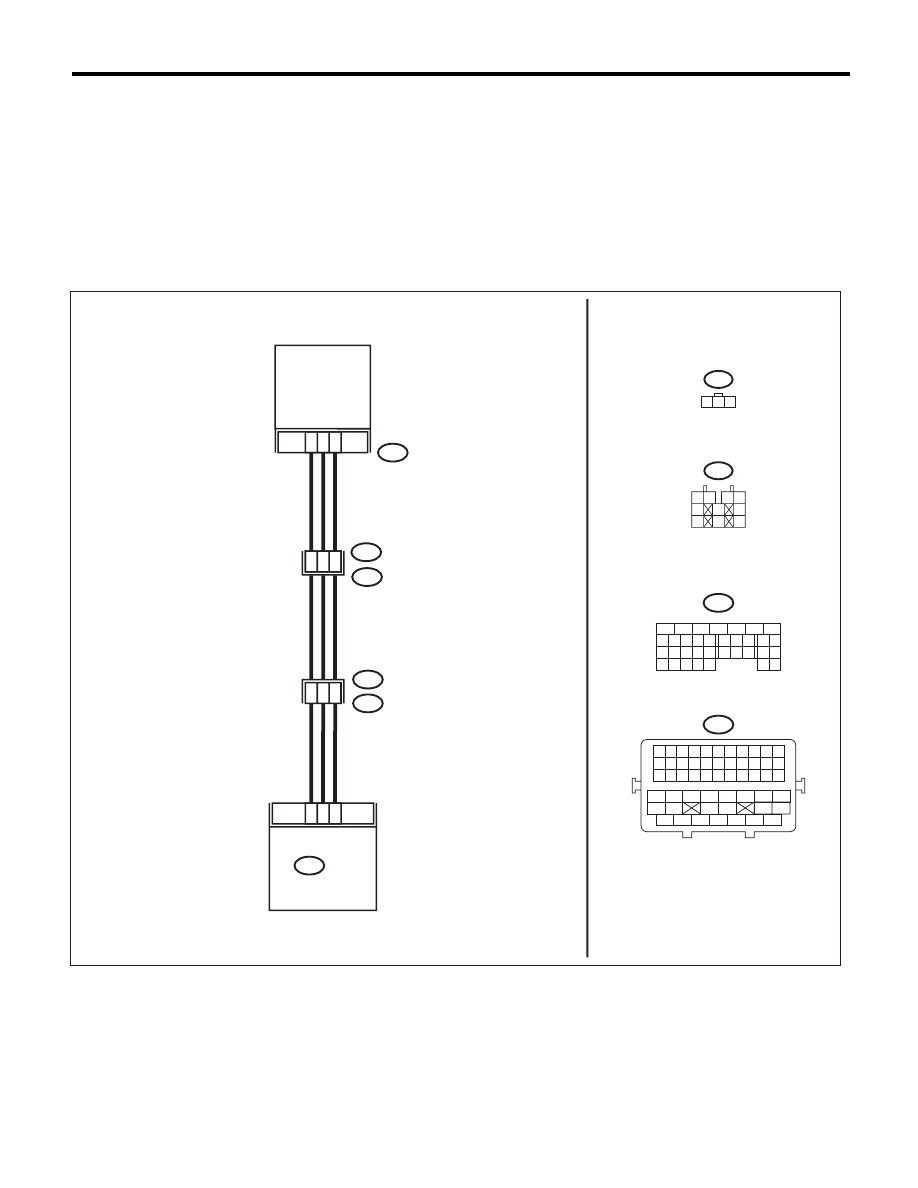
WIRING DIAGRAM:
5
6
7
8
2
1
9
4
3
10
24
22 23
25
11 12 13 14 15
26 27
28
16 17
18 19 20 21
33 34
29
32
30 31
1 2 3
MANIFOLD
ABSOLUTE
PRESSURE
SENSOR
1
3
2
5
8
1
29
6
19
19
20
7
ECM
B134
E21
E77
B21
E2
E76
B134
E21
E77
1 2
3 4
5
6
7
8
9
10
EN-06869
B21
1 2 3 4 5 6 7 8 9 10 11
12 13 14 15 16 17 18 19 20 21 22
23 24 25 26 27 28 29 30 31 32 33
34
35
42
43
36
37
38
39
48
49
50
51
52
53
54
40
41
44
45
46
47

EN(H6DO)(diag)-118
Diagnostic Procedure with Diagnostic Trouble Code (DTC)
ENGINE (DIAGNOSTICS)
Step
Check
Yes
No
1
CHECK AIR INTAKE SYSTEM.
Are there holes, loose bolts or
disconnection of hose on air
intake system?
Repair the air
intake system.
Go to step 2.
2
CHECK MANIFOLD ABSOLUTE PRESSURE
SENSOR.
1) Start the engine and warm up engine until
coolant temperature is higher than 75°C
(167°F).
2) Place the select lever in “P” range or “N”
range.
3) Turn the A/C switch to OFF.
4) Turn all the accessory switches to OFF.
5) Read the data of intake manifold pressure
sensor signal using Subaru Select Monitor or
general scan tool.
NOTE:
• SUBARU SELECT MONITOR
For detailed operation procedure, refer to
“READ CURRENT DATA FOR ENGINE”. <Ref.
to EN(H6DO)(diag)-34, Subaru Select Moni-
tor.>
• General Scan Tool
For detailed operation procedures, refer to the
“General Scan Tool Instruction Manual”.
Is the measured value 73.3 —
106.6 kPa (550 — 800 mmHg,
21.65 — 31.50 inHg) when the
ignition is turned ON, and 20.0 —
46.7 kPa (150 — 350 mmHg,
5.91 — 13.78 inHg) during
idling?
Go to step 3.
Replace the mani-
fold absolute pres-
sure sensor. <Ref.
to FU(H6DO)-25,
Manifold Absolute
Pressure Sensor.>
3
CHECK THROTTLE OPENING ANGLE.
Read the data of throttle position signal using
Subaru Select Monitor or general scan tool.
NOTE:
• SUBARU SELECT MONITOR
For detailed operation procedure, refer to
“READ CURRENT DATA FOR ENGINE”. <Ref.
to EN(H6DO)(diag)-34, Subaru Select Moni-
tor.>
• General Scan Tool
For detailed operation procedures, refer to the
“General Scan Tool Instruction Manual”.
Is the measured value less than
5% when throttle is fully
closed?
Go to step 4.
Replace the elec-
tronic throttle con-
trol. <Ref. to
FU(H6DO)-13,
Throttle Body.>
4
CHECK THROTTLE OPENING ANGLE.
Is the measured value 85% or
more when throttle is fully
open?
Replace the mani-
fold absolute pres-
sure sensor. <Ref.
to FU(H6DO)-25,
Manifold Absolute
Pressure Sensor.>
Replace the elec-
tronic throttle con-
trol. <Ref. to
FU(H6DO)-13,
Throttle Body.>
EN(H6DO)(diag)-119
Diagnostic Procedure with Diagnostic Trouble Code (DTC)
ENGINE (DIAGNOSTICS)
R: DTC P0076 INTAKE VALVE CONTROL SOLENOID CIRCUIT LOW (BANK 1)
DTC DETECTING CONDITION:
• Immediately at fault recognition
• GENERAL DESCRIPTION <Ref. to GD(H6DO)-29, DTC P0076 INTAKE VALVE CONTROL SOLENOID
CIRCUIT LOW (BANK 1), Diagnostic Trouble Code (DTC) Detecting Criteria.>
TROUBLE SYMPTOM:
Improper idling
CAUTION:
After repair or replacement of faulty parts, perform Clear Memory Mode <Ref. to EN(H6DO)(diag)-52,
OPERATION, Clear Memory Mode.>, and Inspection Mode <Ref. to EN(H6DO)(diag)-44, PROCEDURE,
Inspection Mode.>.
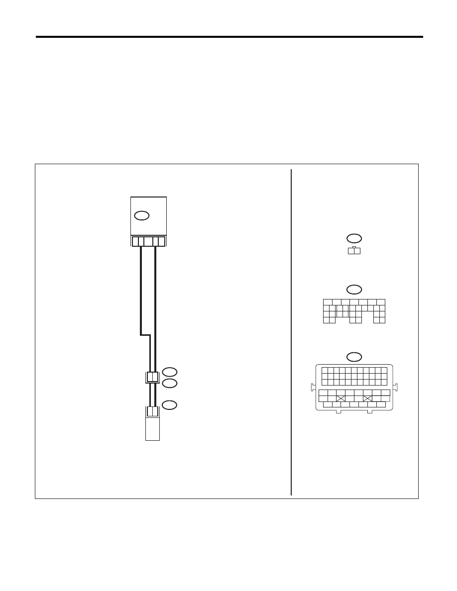
WIRING DIAGRAM:
EN-06870
B21
E2
B137
E69
24
2
1
26
25
E69
1 2
25
ECM
OIL SWITCHING
SOLENOID VALVE RH
B137
5
6
7
8
2
1
9
4
3
10
22 23
11 12 13 14 15
24 25
26
16 17
18 19 20 21
27
28 29
30 31
B21
1 2 3 4 5 6 7 8 9 10 11
12 13 14 15 16 17 18 19 20 21 22
23 24 25 26 27 28 29 30 31 32 33
34
35
42
43
36
37
38
39
48
49
50
51
52
53
54
40
41
44
45
46
47

EN(H6DO)(diag)-120
Diagnostic Procedure with Diagnostic Trouble Code (DTC)
ENGINE (DIAGNOSTICS)
Step
Check
Yes
No
1
CHECK HARNESS BETWEEN ECM AND OIL
SWITCHING SOLENOID VALVE.
1) Turn the ignition switch to OFF.
2) Disconnect the connectors from the ECM
and oil switching solenoid valve.
3) Measure the resistance of harness between
ECM and oil switching solenoid valve.
Connector & terminal
(B137) No. 25 — (E69) No. 1:
(B137) No. 24 — (E69) No. 2:
Is the resistance less than 1
:? Go to step 2.
Repair the harness
and connector.
NOTE:
In this case, repair
the following item:
• Open circuit of
harness between
ECM and oil
switching solenoid
valve connector
• Poor contact of
coupling connector
2
CHECK HARNESS BETWEEN ECM AND OIL
SWITCHING SOLENOID VALVE.
Measure the resistance between ECM and
chassis ground.
Connector & terminal
(B137) No. 25 — Chassis ground:
(B137) No. 24 — Chassis ground:
Is the resistance 1 M
: or
more?
Go to step 3.
Repair the ground
short circuit of har-
ness between
ECM and oil
switching solenoid
valve connector.
3
CHECK OIL SWITCHING SOLENOID VALVE.
Measure the resistance between oil switching
solenoid valve terminals.
Terminals
No. 1 — No. 2:
Is the resistance between 6 —
12
:?
Repair the poor
contact of ECM
and oil switching
solenoid valve con-
nector.
Replace the oil
switching solenoid
valve. <Ref. to
ME(H6DO)-80, Oil
Switching Solenoid
Valve.>
Нет комментариевНе стесняйтесь поделиться с нами вашим ценным мнением.
Текст