Subaru Legacy IV (2008 year). Service manual — part 1055
LI-37
Door Step Light
LIGHTING SYSTEM
33.Door Step Light
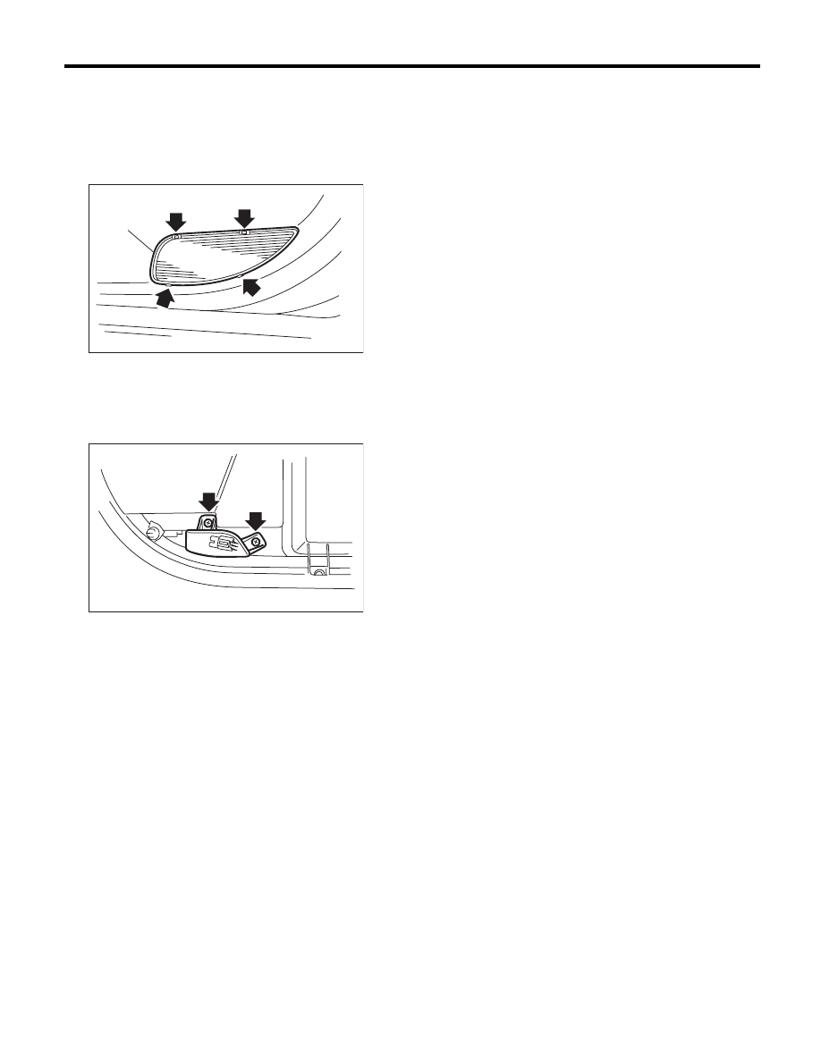
A: REMOVAL
1) Disconnect the ground cable from the battery.
2) Remove lens (A), and then remove the door step
light bulb.
3) Remove the front door trim. <Ref. to EI-49, RE-
MOVAL, Door Trim.>
4) Disconnect the harness connector.
5) Remove the mounting screw from the rear side
of trim and remove the door step light.
B: INSTALLATION
Install in the reverse order of removal.
C: INSPECTION
1) Visually check the bulb for blow out.
2) Check the bulb specification.
<Ref. to LI-2, SPECIFICATION, General Descrip-
tion.>
3) If NG, replace the bulb with a new part.
LI-00266
(A)
LI-00267
LI-38
Ignition Switch Illumination
LIGHTING SYSTEM
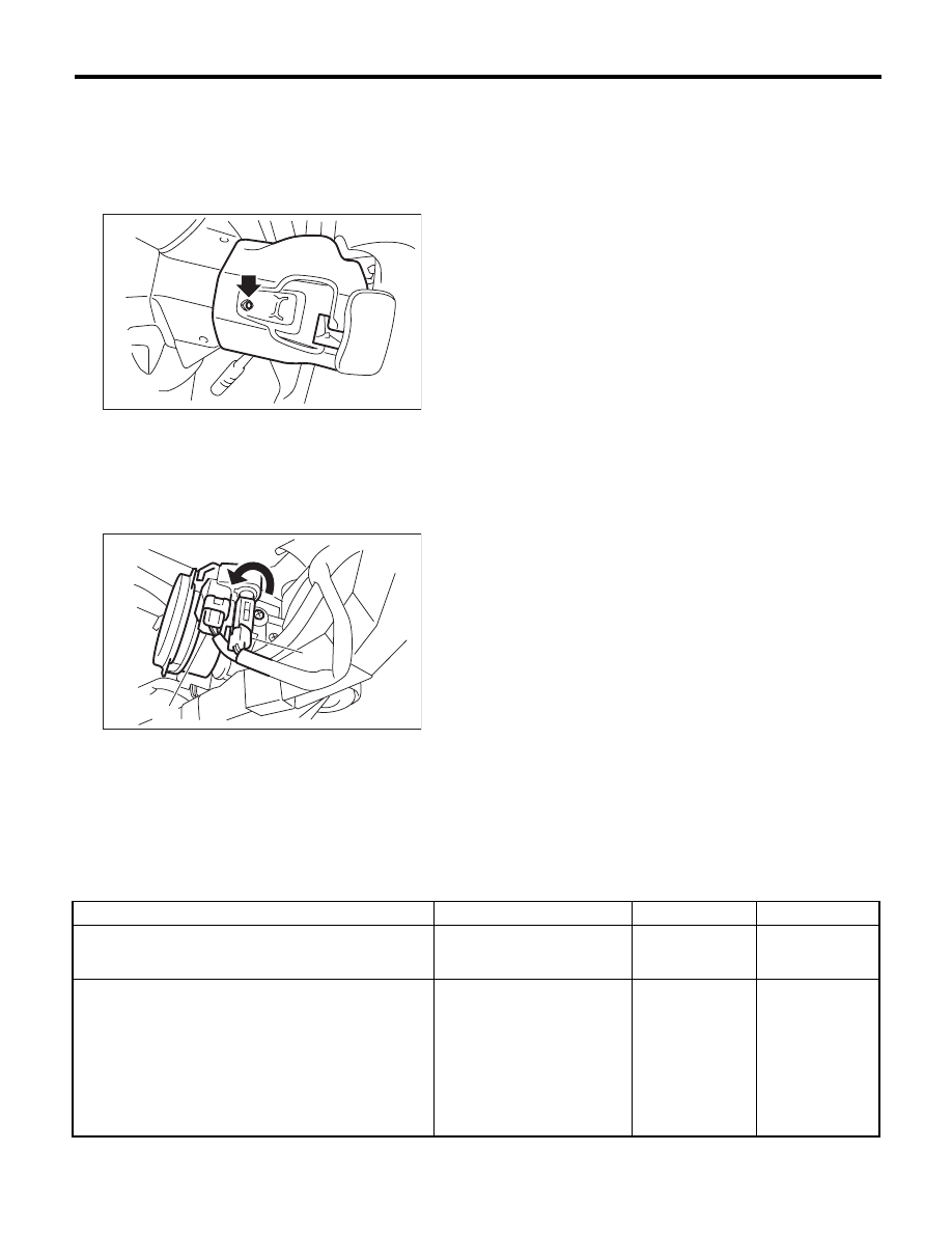
34.Ignition Switch Illumination
A: REMOVAL
1) Disconnect the ground cable from the battery.
2) Remove the screws and remove the steering
column lower cover.
3) Remove the screws and steering column upper
cover.
4) Disconnect the ignition switch illumination con-
nector (A).
5) Turn the ignition switch illumination connector to
the left and disconnect it.
B: INSTALLATION
Install in the reverse order of removal.
C: INSPECTION
(A) Ignition switch illumination connector
(B) Ignition switch illumination
(C) Immobilizer antenna connector
SL-00258
LI-00343
(C)
(B)
(A)
Step
Check
Yes
No
1
CHECK IGNITION SWITCH ILLUMINATION.
Make sure the ignition switch illumination illumi-
nates when driver’s side door is open.
Does the ignition switch illumi-
nation illuminate?
Ignition switch illu-
mination is normal.
Go to step 2.
2
CHECK IGNITION SWITCH ILLUMINATION.
Make sure the ignition switch illumination blinks
when the ignition switch is turned to ON.
Does the ignition switch illumi-
nation blink?
Check the function
setting of the body
integrated unit.
<Ref. to
LAN(diag)-2, Basic
Diagnostic Proce-
dure.>
Check the ignition
switch illumination
circuit. <Ref. to SL-
24, CHECK IGNI-
TION SWITCH
ILLUMINATION,
INSPECTION,
Keyless Entry Sys-
tem.>
LI-39
Day Time Running Light Unit
LIGHTING SYSTEM
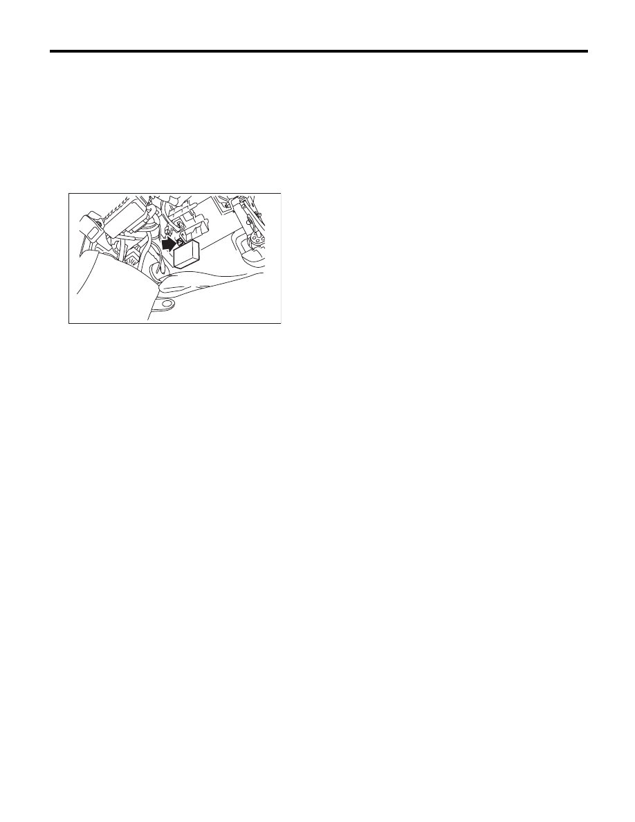
35.Day Time Running Light Unit
A: REMOVAL
1) Remove the instrument panel lower cover. <Ref.
to EI-51, REMOVAL, Instrument Panel Lower Cov-
er.>
2) Remove the fuse box and disconnect the con-
nector.
3) Remove the mounting nuts, and detach the day-
time running light module.
B: INSTALLATION
Install in the reverse order of removal.
Tightening torque:
7.5 N·m (0.76 kgf-m, 5.5 ft-lb)
LI-00753
LI-40
Reflex Reflector
LIGHTING SYSTEM
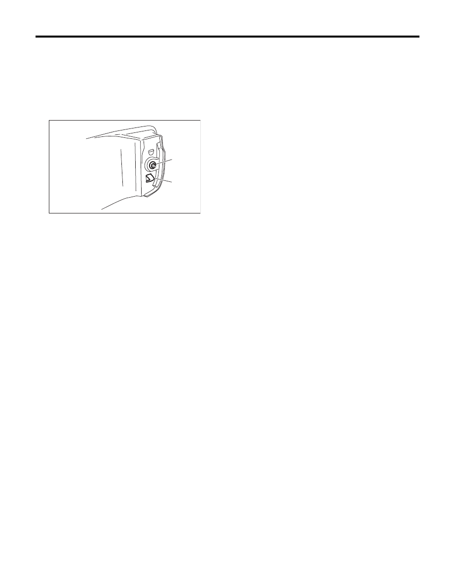
36.Reflex Reflector
A: REMOVAL
1) Remove the rear bumper. <Ref. to EI-37, RE-
MOVAL, Rear Bumper.>
2) Remove the plastic nuts (A).
3) Remove the reflex reflector by pressing the claw
(B) of the reflex reflector.
B: INSTALLATION
Install in the reverse order of removal.
Tightening torque:
4.5 N·m (0.46 kgf-m, 3.3 ft-lb)
LI-00794
(A)
(B)
Нет комментариевНе стесняйтесь поделиться с нами вашим ценным мнением.
Текст