Subaru Legacy IV (2008 year). Service manual — part 475
ME(H6DO)-26
Engine Oil Pressure
MECHANICAL
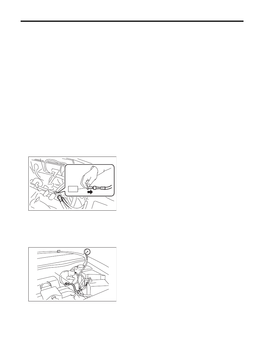
6. Engine Oil Pressure
A: INSPECTION
1) Remove the oil pressure switch from the cylinder
block. <Ref. to LU(H6DO)-15, REMOVAL, Oil
Pressure Switch.>
2) Connect the oil pressure gauge hose to the cyl-
inder block.
3) Connect the ground cable to battery.
4) Start the engine, and measure the oil pressure.
OIL PRESSURE (at oil temperature of 80°C
(176°F)):
Standard:
135 kPa (1.4 kgf/cm
2
, 20 psi) or more
(at 600 rpm)
500 kPa (5.1 kgf/cm
2
, 73 psi) or more
(at 5,000 rpm)
• If the oil pressure is out of specification, check oil
pump, oil filter and lubrication line. <Ref. to
LU(H6DO)-19, INSPECTION, Engine Lubrication
System Trouble in General.>
• If the oil pressure warning light is ON and oil
pressure is within specification, check the oil pres-
sure switch. <Ref. to LU(H6DO)-19, INSPECTION,
Engine Lubrication System Trouble in General.>
5) After measuring the oil pressure, install the oil
pressure switch. <Ref. to LU(H6DO)-15, INSTAL-
LATION, Oil Pressure Switch.>
ME(H6DO)-27
Fuel Pressure
MECHANICAL
7. Fuel Pressure
A: INSPECTION
CAUTION:
• Before removing the fuel pressure gauge, re-
lease the fuel pressure.
• Be careful not to spill fuel.
• Catch the fuel from hoses using a container
or cloth.
NOTE:
Check or replace the fuel pump and fuel delivery
line if the fuel pressure is out of the standard.
1) Remove the collector cover.
2) Release the fuel pressure. <Ref. to FU(H6DO)-
43, RELEASING OF FUEL PRESSURE, PROCE-
DURE, Fuel.>
3) Open the fuel filler lid, and remove the fuel filler
cap.
4) Disconnect the fuel delivery hose and connect
the fuel pressure gauge.
(1) Disconnect the fuel delivery hose using the
ST1.
ST1
42099AE000 QUICK CONNECTOR
RELEASE
(2) Connect the fuel pressure gauge with ST2
and ST3.
NOTE:
ST2 is a SUBARU genuine part.
ST2
42075AG690 FUEL HOSE
ST3
18471AA000 FUEL PIPE ADAPTER
5) Start the engine.
6) Measure the fuel pressure after warming up the
engine.
Fuel pressure:
Standard: 338 — 348 kPa
(3.4 — 3.5 kgf/cm
2
, 49 — 50.5 psi)
NOTE:
The fuel pressure gauge registers 10 to 20 kPa (0.1
to 0.2 kgf/cm
2
, 1 to 3 psi) higher than standard val-
ues during high-altitude operations.
(A) ST2
(B) ST3
FU-02676
ST
(A)
(B)
ME-02666
ME(H6DO)-28
Valve Clearance
MECHANICAL
8. Valve Clearance
A: INSPECTION
NOTE:
Inspection and adjustment of valve clearance
should be performed while engine is cold.
1) Set the vehicle on a lift.
2) Remove the collector cover.
3) Disconnect the ground cable from the battery.
4) Lift up the vehicle.
5) Remove the under cover.
6) Lower the vehicle.
7) When inspecting RH side cylinders:
(1) Remove the air intake duct and air cleaner
case. <Ref. to IN(H6DO)-8, REMOVAL, Air In-
take Duct.> <Ref. to IN(H6DO)-5, REMOVAL,
Air Cleaner Case.>
(2) Remove the fuel pipe protector (RH).
(3) Disconnect the connector of oil pressure
switch.
(4) Remove the ignition coil. <Ref. to
IG(H6DO)-7, REMOVAL, Ignition Coil.>
(5) Remove the rocker cover (RH).
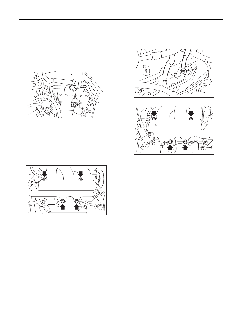
8) When inspecting LH side cylinders:
(1) Disconnect the battery cable, and then re-
move the battery and battery carrier.
(2) Disconnect the PCV hose and blow-by hose
from the rocker cover (LH).
(3) Remove the fuel pipe protector (LH).
(4) Remove the ignition coil. <Ref. to
IG(H6DO)-7, REMOVAL, Ignition Coil.>
(5) Remove the rocker cover (LH).
IN-00203
FU-02119
ME-00460
FU-02117
ME(H6DO)-29
Valve Clearance
MECHANICAL
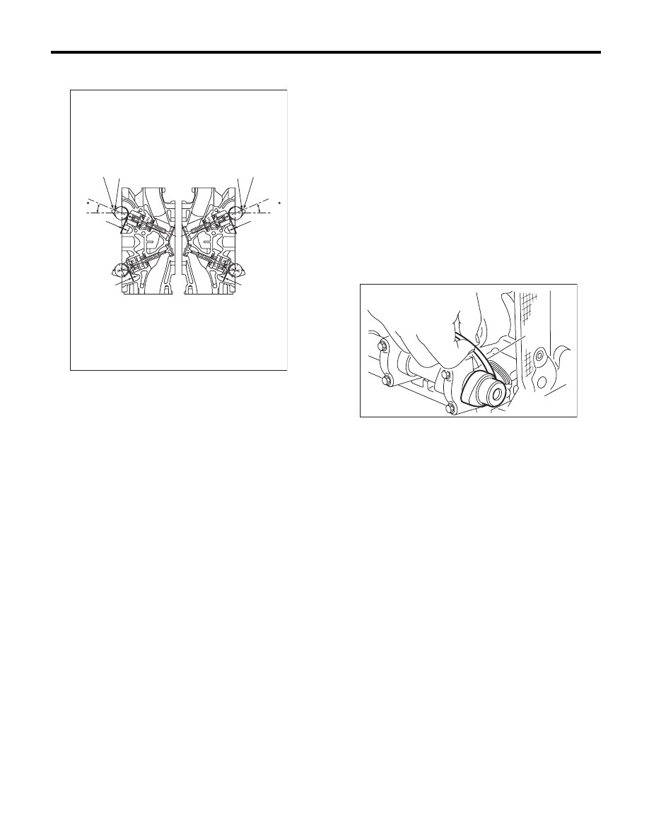
9) Turn the crankshaft clockwise until the cam is
set to position shown in the figure.
10) Measure the clearance of intake valve and ex-
haust valve using thickness gauge (A).
NOTE:
• Measure it within the range of
r30° from speci-
fied position shown in the figure.
• Measure it in low lift cam for intake side.
• Insert a thickness gauge in a direction as hori-
zontal as possible with respect to the valve lifter.
Valve clearance
Intake:
0.20
+0.04
–0.06
mm (0.0079
+0.0016
–0.0024
in)
Exhaust:
0.35
r
0.05 mm (0.0138
r
0.0020 in)
• If the measured value is not within specification,
take notes of the value in order to adjust the valve
clearance later on.
11) If necessary, adjust the valve clearance. <Ref.
to ME(H6DO)-30, ADJUSTMENT, Valve Clear-
ance.>
12) Further turn the crank pulley clockwise and
then measure the valve clearances again.
13) After inspection, install the related parts in the
reverse order of removal.
(1) Valve clearance (Intake side)
(2) Valve clearance (Exhaust side)
(3) High lift cam
(4) Low lift cam
ME-02565
(4)
(3)
(3)
(4)
(1)
(2)
(1)
(2)
(23 )
(23 )
(A)
ME-00464
Нет комментариевНе стесняйтесь поделиться с нами вашим ценным мнением.
Текст