Subaru Legacy IV (2008 year). Service manual — part 476
ME(H6DO)-30
Valve Clearance
MECHANICAL
B: ADJUSTMENT
1. INTAKE SIDE
NOTE:
• Adjustment of valve clearance should be per-
formed while engine is cold.
• Do not wear gloves during removal and installa-
tion of valve lifter.
• Do not use valve lifters that were dropped or oth-
erwise exposed to strong impacts.
• When installing the valve lifter, align the anti-ro-
tation of valve lifter with groove on cylinder head,
and insert the valve lifter.
1) Measure all the valve clearances. <Ref. to
ME(H6DO)-28, INSPECTION, Valve Clearance.>
NOTE:
Record each valve clearance after measurement.
2) Remove the timing chain assembly. <Ref. to
ME(H6DO)-46, REMOVAL, Timing Chain Assem-
bly.>
3) Remove the cam sprocket. <Ref. to ME(H6DO)-
51, REMOVAL, Cam Sprocket.>
4) Remove the camshaft. <Ref. to ME(H6DO)-55,
REMOVAL, Camshaft.>
5) Remove the valve lifter.
6) Remove the shim from valve lifter.
7) Check the thickness of the shim from the mark-
ings on the side of the shim that was removed.
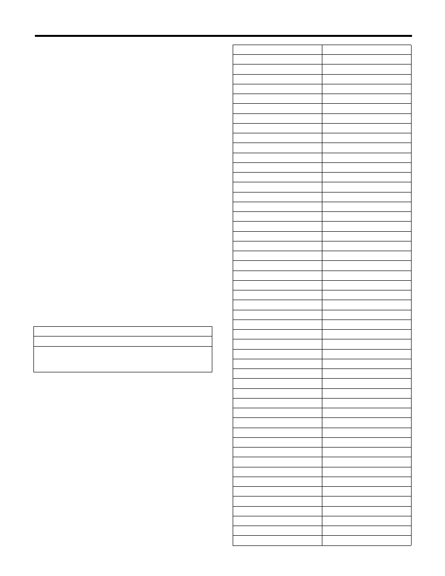
8) Select a shim of suitable thickness from the fol-
lowing table using the measured valve clearance
and shim thickness, and install it.
Unit: mm (in)
S = (V + T) – 0.20 (0.0079)
S: Required shim thickness
V: Measured valve clearance
T: Shim thickness to be used
Part No.
Thickness mm (in)
13218AK890
1.92 (0.0756)
13218AK900
1.94 (0.0764)
13218AK910
1.96 (0.0772)
13218AK920
1.98 (0.0780)
13218AK930
2.00 (0.0787)
13218AK940
2.02 (0.0795)
13218AK950
2.04 (0.0803)
13218AK960
2.06 (0.0811)
13218AK970
2.07 (0.0815)
13218AK980
2.08 (0.0819)
13218AK990
2.09 (0.0823)
13218AL000
2.10 (0.0827)
13218AL010
2.11 (0.0831)
13218AL020
2.12 (0.0835)
13218AL030
2.13 (0.0839)
13218AL040
2.14 (0.0843)
13218AL050
2.15 (0.0846)
13218AL060
2.16 (0.0850)
13218AL070
2.17 (0.0854)
13218AL080
2.18 (0.0858)
13218AL090
2.19 (0.0862)
13218AL100
2.20 (0.0866)
13218AL110
2.21 (0.0870)
13218AL120
2.22 (0.0874)
13218AL130
2.23 (0.0878)
13218AL140
2.24 (0.0882)
13218AL150
2.25 (0.0886)
13218AL160
2.26 (0.0890)
13218AL170
2.27 (0.0894)
13218AL180
2.28 (0.0898)
13218AL190
2.29 (0.0902)
13218AL200
2.30 (0.0906)
13218AL210
2.31 (0.0909)
13218AL220
2.32 (0.0913)
13218AL230
2.33 (0.0917)
13218AL240
2.34 (0.0921)
13218AL250
2.35 (0.0925)
13218AL260
2.36 (0.0929)
13218AL270
2.37 (0.0933)
13218AL280
2.38 (0.0937)
13218AL290
2.39 (0.0941)
13218AL300
2.40 (0.0945)
13218AL310
2.41 (0.0949)
13218AL320
2.42 (0.0953)
13218AL330
2.43 (0.0957)
13218AL340
2.44 (0.0961)
13218AL350
2.45 (0.0965)
13218AL360
2.46 (0.0969)
13218AL370
2.47 (0.0972)
13218AL380
2.48 (0.0976)
ME(H6DO)-31
Valve Clearance
MECHANICAL
9) Install the camshaft. <Ref. to ME(H6DO)-56, IN-
STALLATION, Camshaft.>
10) Install the cam sprocket. <Ref. to ME(H6DO)-
51, INSTALLATION, Cam Sprocket.>
11) Install the timing chain assembly. <Ref. to
ME(H6DO)-47, INSTALLATION, Timing Chain As-
sembly.>
12) Measure all valve clearance again at this time.
If the valve clearance is not correct, repeat the pro-
cedure over again from the first step.
13) After measuring, install the related parts in the
reverse order of removal.
NOTE:
Use a new rocker cover gasket.
2. EXHAUST SIDE
NOTE:
• Adjustment of valve clearance should be per-
formed while engine is cold.
• Do not wear gloves during removal and installa-
tion of valve lifter.
• Do not use valve lifters that were dropped or oth-
erwise exposed to strong impacts.
1) Measure all the valve clearances. <Ref. to
ME(H6DO)-28, INSPECTION, Valve Clearance.>
NOTE:
Record each valve clearance after measurement.
2) Remove the camshaft. <Ref. to ME(H6DO)-55,
REMOVAL, Camshaft.>
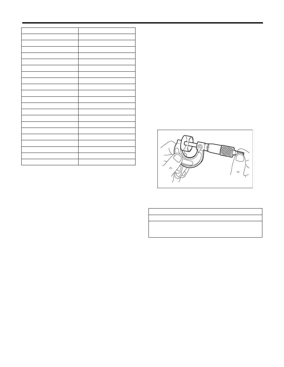
3) Remove the valve lifter.
4) Measure the thickness of valve lifter using mi-
crometer.
5) Select a valve lifter of suitable thickness from the
following table using the measured valve clearance
and valve lifter thickness, and install it.
13218AL390
2.49 (0.0980)
13218AL400
2.50 (0.0984)
13218AL410
2.51 (0.0988)
13218AL420
2.52 (0.0992)
13218AL430
2.53 (0.0996)
13218AL440
2.54 (0.1000)
13218AL450
2.55 (0.1004)
13218AL460
2.56 (0.1008)
13218AL470
2.57 (0.1012)
13218AL480
2.58 (0.1016)
13218AL490
2.59 (0.1020)
13218AL500
2.60 (0.1024)
13218AL510
2.61 (0.1028)
13218AL520
2.62 (0.1032)
13218AL530
2.64 (0.1039)
13218AL540
2.66 (0.1047)
13218AL550
2.68 (0.1055)
13218AL560
2.70 (0.1063)
13218AL570
2.72 (0.1071)
13218AL580
2.74 (0.1079)
13218AL590
2.76 (0.1087)
Part No.
Thickness mm (in)
Unit: mm (in)
S = (V + T) – 0.35 (0.0138)
S: Valve lifter thickness required
V: Measured valve clearance
T: Valve lifter thickness to be used
ME-00025

ME(H6DO)-32
Valve Clearance
MECHANICAL
Part No.
Thickness mm (in)
13228AD181
4.32 (0.1701)
13228AD191
4.34 (0.1709)
13228AD201
4.36 (0.1717)
13228AD211
4.38 (0.1724)
13228AD221
4.40 (0.1732)
13228AD231
4.42 (0.1740)
13228AD241
4.44 (0.1748)
13228AD251
4.46 (0.1756)
13228AD261
4.48 (0.1764)
13228AD271
4.50 (0.1772)
13228AD281
4.52 (0.1780)
13228AD291
4.54 (0.1787)
13228AD301
4.56 (0.1795)
13228AD311
4.58 (0.1803)
13228AD321
4.60 (0.1811)
13228AC581
4.62 (0.1819)
13228AC591
4.63 (0.1823)
13228AC601
4.64 (0.1827)
13228AC611
4.65 (0.1831)
13228AC621
4.66 (0.1835)
13228AC631
4.67 (0.1839)
13228AC641
4.68 (0.1843)
13228AC651
4.69 (0.1846)
13228AC661
4.70 (0.1850)
13228AC671
4.71 (0.1854)
13228AC681
4.72 (0.1858)
13228AC691
4.73 (0.1862)
13228AC701
4.74 (0.1866)
13228AC711
4.75 (0.1870)
13228AC721
4.76 (0.1874)
13228AC731
4.77 (0.1878)
13228AC741
4.78 (0.1882)
13228AC751
4.79 (0.1886)
13228AC761
4.80 (0.1890)
13228AC771
4.81 (0.1894)
13228AC781
4.82 (0.1898)
13228AC791
4.83 (0.1902)
13228AC801
4.84 (0.1906)
13228AC811
4.85 (0.1909)
13228AC821
4.86 (0.1913)
13228AC831
4.87 (0.1917)
13228AC841
4.88 (0.1921)
13228AC851
4.89 (0.1925)
13228AC861
4.90 (0.1929)
13228AC871
4.91 (0.1933)
13228AC881
4.92 (0.1937)
13228AC891
4.93 (0.1941)
13228AC901
4.94 (0.1945)
13228AC911
4.95 (0.1949)
13228AC921
4.96 (0.1953)
13228AC931
4.97 (0.1957)
13228AC941
4.98 (0.1961)
13228AC951
4.99 (0.1965)
13228AC961
5.00 (0.1969)
13228AC971
5.01 (0.1972)
13228AC981
5.02 (0.1976)
13228AC991
5.03 (0.1980)
13228AD001
5.04 (0.1984)
13228AD011
5.05 (0.1988)
13228AD021
5.06 (0.1992)
13228AD031
5.07 (0.1996)
13228AD041
5.08 (0.2000)
13228AD051
5.09 (0.2004)
13228AD061
5.10 (0.2008)
13228AD071
5.11 (0.2012)
13228AD081
5.12 (0.2016)
13228AD091
5.13 (0.2020)
13228AD101
5.14 (0.2024)
13228AD111
5.15 (0.2028)
13228AD121
5.16 (0.2032)
13228AD131
5.17 (0.2035)
13228AD141
5.18 (0.2039)
13228AD151
5.19 (0.2043)
13228AD161
5.20 (0.2047)
13228AD171
5.21 (0.2051)
13228AD331
5.23 (0.2059)
13228AD341
5.25 (0.2067)
13228AD351
5.27 (0.2075)
13228AD361
5.29 (0.2083)
13228AD371
5.31 (0.2091)
13228AD381
5.33 (0.2098)
13228AD391
5.35 (0.2106)
13228AD401
5.37 (0.2114)
13228AD411
5.39 (0.2122)
13228AD421
5.41 (0.2130)
13228AD431
5.43 (0.2138)
13228AD441
5.45 (0.2146)
13228AD451
5.47 (0.2154)
13228AD461
5.49 (0.2161)
13228AD471
5.51 (0.2169)
13228AD481
5.53 (0.2177)
13228AD491
5.55 (0.2185)
13228AD501
5.57 (0.2193)
13228AD511
5.59 (0.2201)
Part No.
Thickness mm (in)
ME(H6DO)-33
Valve Clearance
MECHANICAL
6) Install the camshaft. <Ref. to ME(H6DO)-56, IN-
STALLATION, Camshaft.>
7) Install the cam sprocket. <Ref. to ME(H6DO)-51,
INSTALLATION, Cam Sprocket.>
8) Install the timing chain assembly. <Ref. to
ME(H6DO)-47, INSTALLATION, Timing Chain As-
sembly.>
9) Measure all valve clearance again at this time. If
the valve clearance is not correct, repeat the proce-
dure over again from the first step.
10) After measuring, install the related parts in the
reverse order of removal.
NOTE:
Use a new rocker cover gasket.
Нет комментариевНе стесняйтесь поделиться с нами вашим ценным мнением.
Текст