Subaru Legacy IV (2008 year). Service manual — part 1067
ET-25
Steering Satellite Switch
ENTERTAINMENT
19.Steering Satellite Switch
A: REMOVAL
WARNING:
Before servicing, be sure to read the notes in
the “AB” section for proper handling of the
driver’s airbag module. <Ref. to AB-4, CAU-
TION, General Description.>
1) Set the front wheels in straight ahead position.
2) Turn the ignition switch to OFF.
3) Disconnect the ground cable from battery and
wait for at least 20 seconds before starting work.
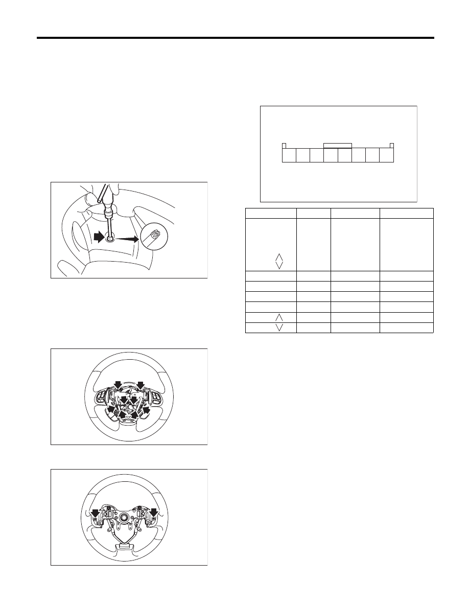
4) Using TORX
®
bit T30 (1), loosen the two TORX
®
bolts which secure the driver’s airbag module.
5) Disconnect the airbag module connector on
back of the airbag module. <Ref. to AB-8, PROCE-
DURE, Airbag Connector.>
6) Remove the steering wheel. <Ref. to PS-13, RE-
MOVAL, Steering Wheel.>
7) Remove the screws to remove the lower cover
from steering wheel.
8) Loosen the screws on the backside of the steer-
ing wheel and remove the satellite switch.
B: INSTALLATION
Install in the reverse order of removal.
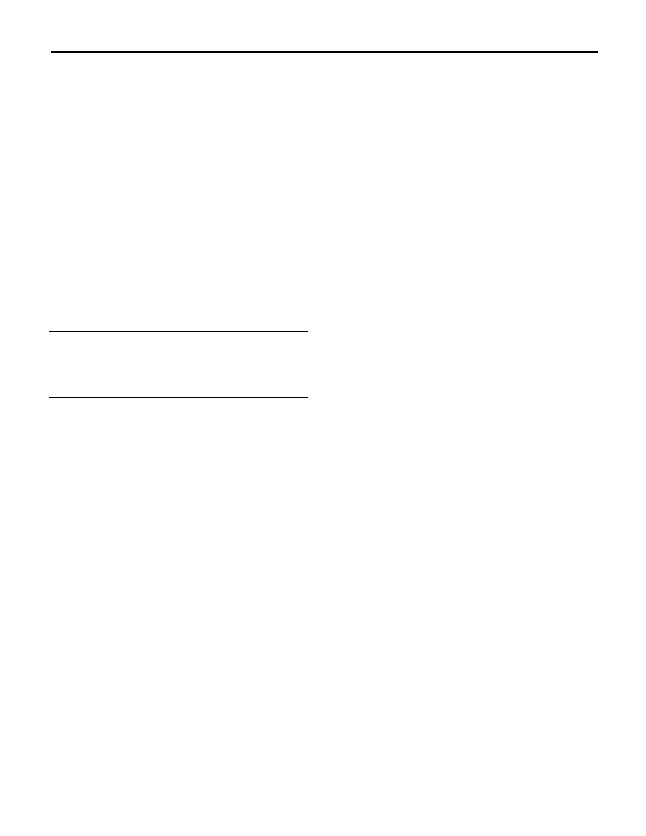
C: INSPECTION
Measure the resistance between satellite switch
connector terminals.
Replace the satellite switch if defective.
CC-00018
(1)
CC-00515
CC-00516
Switch
Area
Terminal No.
Standard
Mute
Volume (+)
Volume (–)
Mode
Seek (
)
Seek (
)
All OFF
4 and 5
Approx. 4.7 k
:
Mute
ON
4 and 5
Approx. 22
:
Volume (+)
ON
4 and 5
Approx. 90
:
Volume (–)
ON
4 and 5
Approx. 200
:
Mode
ON
4 and 5
Approx. 360
:
Seek (
)
ON
4 and 5
Approx. 690
:
Seek (
)
ON
4 and 5
Approx. 1.5 k
:
CC-00487
2 3
1
4 5 6 7 8
ET-26
Steering Satellite Switch
ENTERTAINMENT
COM-2
General Description
COMMUNICATION SYSTEM
1. General Description
A: CAUTION
• Before disassembling or reassembling parts, al-
ways disconnect the battery ground cable from bat-
tery. When replacing the audio, control module and
other parts provided with memory functions, record
the memory contents before disconnecting the bat-
tery ground cable. Otherwise, the memory is
cleared.
• Reassemble the parts in the reverse order of dis-
assembly procedure unless otherwise indicated.
• Adjust parts to the given specifications.
• Connect the connectors securely during reas-
sembly.
• After reassembly, make sure functional parts op-
erate smoothly.
B: PREPARATION TOOL
1. GENERAL TOOL
TOOL NAME
REMARKS
Circuit tester
Used for measuring resistance and
voltage.
TORX
®
bit T30
Used for removing/installing driver’s
airbag module.
COM-3
Horn System
COMMUNICATION SYSTEM
2. Horn System
A: WIRING DIAGRAM
1. HORN
<Ref. to WI-159, WIRING DIAGRAM, Horn Sys-
tem.>
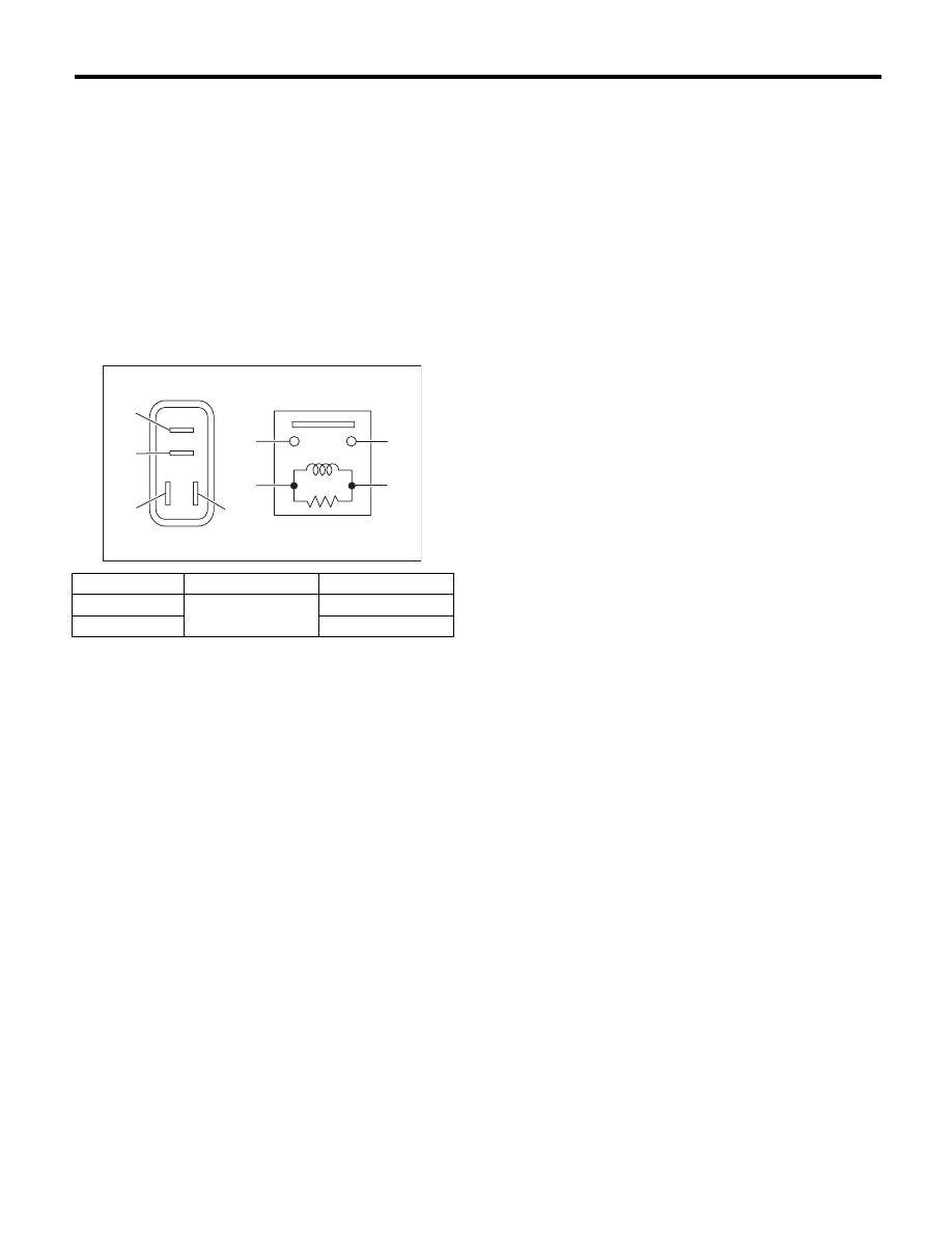
B: INSPECTION
1. HORN RELAY
Measure the security horn relay resistance be-
tween terminals (indicated in the table below) when
connecting terminal No. 4 to battery positive termi-
nal and terminal No. 3 to battery ground terminal.
Continuity
Terminal No.
Standard
Yes
1 and 2
Less than 1
:
No
1 M
: or more
COM00001
(1)
(2)
(1)
(4)
(2)
(3)
(3)
(4)
Нет комментариевНе стесняйтесь поделиться с нами вашим ценным мнением.
Текст