Subaru Legacy IV (2008 year). Service manual — part 359
EN(H4DOTC)(diag)-257
Diagnostic Procedure with Diagnostic Trouble Code (DTC)
ENGINE (DIAGNOSTICS)
CO:DTC P1153 O2 SENSOR CIRCUIT RANGE/PERFORMANCE (HIGH) (BANK1
SENSOR1)
DTC DETECTING CONDITION:
• Two consecutive driving cycles with fault
• GENERAL DESCRIPTION <Ref. to GD(H4DOTC)-168, DTC P1153 O2 SENSOR CIRCUIT RANGE/
PERFORMANCE (HIGH) (BANK1 SENSOR1), Diagnostic Trouble Code (DTC) Detecting Criteria.>
CAUTION:
After repair or replacement of faulty parts, perform Clear Memory Mode <Ref. to EN(H4DOTC)(diag)-
52, OPERATION, Clear Memory Mode.>, and Inspection Mode <Ref. to EN(H4DOTC)(diag)-43, PRO-
CEDURE, Inspection Mode.>.
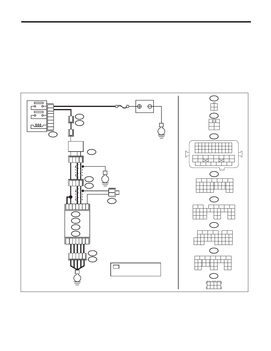
WIRING DIAGRAM:
EN-05669
SBF-5
B47
B21
E2
B21
E2
1
2
4
6
3
5
E
E
C2
C3
B8
B9
B1
B134
4
3
2
1
E79
3 4
1 2
3
4
1
2
5
6
B21
B47
E79
B134
5
6
7
8
2
1
9
4
3
10
24
22 23
25
11 12 13 14 15
26 27
28
16 17
18 19 20 21
33 34
29
32
30 31
A:
B135
B:
B136
C:
B137
D:
1 2 3 4
12 13 14 15
5 6 7 8
16 17 18 19
9 10 11
20 21 22
23 24 25 26 27 28 29 30 31 32 33
35
34
37
36
39
38
41
40
43
42
44
45
47
46
49
48
51
50
53
52
54
A:
D2
A5
D3
E2
B21
E
35
34
40
D7
36
D1
37
B138
*
*
*
16
10 11 12 13 14 15
25
24
30
9
8
7
17 18 19 20
28
21 22 23
29
32
31
1
2
3
4
5
6
27
26
33 34 35
B136
C:
B135
5
6
7
8
2
1
9
4
3
10
24
22 23
25
11 12 13 14 15
26 27
28
16 17 18 19
20 21
29 30 31
32 33
34 35
B137
5
6
7
8
2
1
9
4
3
10
22 23
11 12 13 14 15
24 25
26
16 17
18 19 20 21
27
28 29
30 31
B:
D:
1 2 3 4
5 6 7 8
B138
42
26
43
15
MAIN RELAY
BATTERY
FRONT
OXYGEN (A/F)
SENSOR
ECM
: TERMINAL No. OPTIONAL
ARRANGEMENT
AMONG 1, 2, 5 AND 6

EN(H4DOTC)(diag)-258
Diagnostic Procedure with Diagnostic Trouble Code (DTC)
ENGINE (DIAGNOSTICS)
CP:DTC P1160 RETURN SPRING FAILURE
NOTE:
For the diagnostic procedure, refer to DTC P2101. <Ref. to EN(H4DOTC)(diag)-318, DTC P2101 THROT-
TLE ACTUATOR CONTROL MOTOR CIRCUIT RANGE/PERFORMANCE, Diagnostic Procedure with Di-
agnostic Trouble Code (DTC).>
Step
Check
Yes
No
1
CHECK FRONT OXYGEN (A/F) SENSOR
CONNECTOR AND COUPLING CONNEC-
TOR.
Has water entered the connec-
tor?
Completely
remove any water
inside.
Go to step 2.
2
CHECK HARNESS BETWEEN ECM AND
FRONT OXYGEN (A/F) SENSOR CONNEC-
TOR.
1) Turn the ignition switch to OFF.
2) Disconnect the connectors from ECM.
3) Measure the resistance between ECM and
chassis ground.
Connector & terminal
(B135) No. 9 — Chassis ground:
(B135) No. 8 — Chassis ground:
Is the resistance 1 M
: or
more?
Go to step 3.
Repair the ground
short circuit of har-
ness between
ECM and front oxy-
gen (A/F) sensor
connector.
3
CHECK OUTPUT SIGNAL FOR ECM.
1) Connect the connector to ECM.
2) Turn the ignition switch to ON.
3) Measure the voltage between ECM and
chassis ground.
Connector & terminal
(B135) No. 9 (+) — Chassis ground (–):
Is the voltage 4.5 V or more?
Go to step 5.
Go to step 4.
4
CHECK OUTPUT SIGNAL FOR ECM.
Measure the voltage between ECM and chassis
ground.
Connector & terminal
(B135) No. 8 (+) — Chassis ground (–):
Is the voltage 4.95 V or more?
Go to step 5.
Replace the front
oxygen (A/F) sen-
sor. <Ref. to
FU(H4DOTC)-46,
Front Oxygen (A/F)
Sensor.>
5
CHECK OUTPUT SIGNAL FOR ECM.
Measure the voltage between ECM and chassis
ground.
Connector & terminal
(B135) No. 9 (+) — Chassis ground (–):
(B135) No. 8 (+) — Chassis ground (–):
Is the voltage 8 V or more?
Repair the short
circuit to power in
the harness
between ECM and
front oxygen (A/F)
sensor connector.
After repair,
replace the ECM.
<Ref. to
FU(H4DOTC)-52,
Engine Control
Module (ECM).>
Repair the poor
contact of ECM
connector.
EN(H4DOTC)(diag)-259
Diagnostic Procedure with Diagnostic Trouble Code (DTC)
ENGINE (DIAGNOSTICS)
CQ:DTC P1400 FUEL TANK PRESSURE CONTROL SOLENOID VALVE CIRCUIT
LOW
DTC DETECTING CONDITION:
• Two consecutive driving cycles with fault
• GENERAL DESCRIPTION <Ref. to GD(H4DOTC)-172, DTC P1400 FUEL TANK PRESSURE CONTROL
SOLENOID VALVE CIRCUIT LOW, Diagnostic Trouble Code (DTC) Detecting Criteria.>
CAUTION:
After repair or replacement of faulty parts, perform Clear Memory Mode <Ref. to EN(H4DOTC)(diag)-
52, OPERATION, Clear Memory Mode.>, and Inspection Mode <Ref. to EN(H4DOTC)(diag)-43, PRO-
CEDURE, Inspection Mode.>.
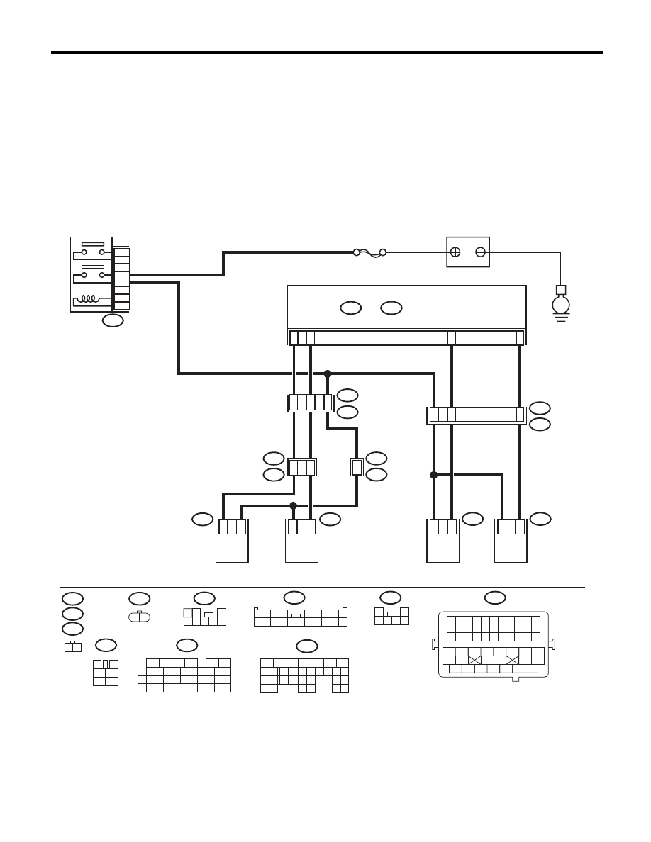
WIRING DIAGRAM:
EN-05679
SBF-7
E4
B47
E
5
3
6
4
2
1
2
1
C17
C28
D29
C7
R15
R213
R68
R144
R1
B97
14
15
2
2
1
1
7
1
5
E52
2
1
E52
R144
E4
B47
R67
B97
R213
R68
1 2
3
4
1
2
5
6
B21
1 2
1 2
3
4 5 6 7 8
1 2 3 4 5 6 7 8 9 10 11
12 13 14 15 16 17 18 19 20 21 22
23 24 25 26 27 28 29 30 31 32 33
34
35
42
43
36
37
38
39
48
49
50
51
52
53
54
40
41
44
45
46
47
1
2
3 4 5 6
1 2 3 4
5 6 7 8 9
10 11 12 13 14 15 16 17 18 19 20
R46
R67
6
B21
E2
11
48
16
10 11 12 13 14 15
25
24
30
9
8
7
17 18 19 20
28
21 22 23
29
32
31
1
2
3
4
5
6
27
26
33 34 35
B136
C:
B137
5
6
7
8
2
1
9
4
3
10
22 23
11 12 13 14 15
24 25
26
16 17
18 19 20 21
27
28 29
30 31
D:
B136
C:
B137
D:
44
MAIN RELAY
ECM
BATTERY
DRAIN VALVE
PRESSURE
CONTROL
SOLENOID VALVE
PURGE CONTROL
SOLENOID VALVE 1
PURGE CONTROL
SOLENOID VALVE 2

EN(H4DOTC)(diag)-260
Diagnostic Procedure with Diagnostic Trouble Code (DTC)
ENGINE (DIAGNOSTICS)
Step
Check
Yes
No
1
CHECK OUTPUT SIGNAL OF ECM.
1) Turn the ignition switch to ON.
2) Measure the voltage between ECM and
chassis ground.
Connector & terminal
(B136) No. 28 (+) — Chassis ground (–):
Is the voltage 10 V or more?
Repair the poor
contact of ECM
connector.
Go to step 2.
2
CHECK HARNESS BETWEEN ECM AND
PRESSURE CONTROL SOLENOID VALVE.
1) Turn the ignition switch to OFF.
2) Disconnect the connector from the ECM
and pressure control solenoid valve.
3) Measure the resistance between pressure
control solenoid valve and chassis ground.
Connector & terminal
(R68) No. 2 — Chassis ground:
Is the resistance 1 M
: or
more?
Go to step 3.
Repair the ground
short circuit of har-
ness between
ECM and pressure
control solenoid
valve connector.
3
CHECK HARNESS BETWEEN ECM AND
PRESSURE CONTROL SOLENOID VALVE.
Measure the resistance of harness between
ECM and pressure control solenoid valve con-
nector.
Connector & terminal
(B136) No. 28 — (R68) No. 2:
Is the resistance less than 1
:? Go to step 4.
Repair the harness
and connector.
NOTE:
In this case, repair
the following item:
• Open circuit in
harness between
ECM and pressure
control solenoid
valve connector
• Poor contact of
coupling connector
4
CHECK PRESSURE CONTROL SOLENOID
VALVE.
Measure the resistance between pressure con-
trol solenoid valve terminals.
Terminals
No. 1 — No. 2:
Is the resistance between 10 —
100
:?
Go to step 5.
Replace the pres-
sure control sole-
noid valve. <Ref. to
EC(H4DOTC)-16,
Pressure Control
Solenoid Valve.>
5
CHECK POWER SUPPLY TO THE PRES-
SURE CONTROL SOLENOID VALVE.
1) Turn the ignition switch to ON.
2) Measure the voltage between pressure con-
trol solenoid valve and chassis ground.
Connector & terminal
(R68) No. 1 (+) — Chassis ground (–):
Is the voltage 10 V or more?
Repair the poor
contact of pressure
control solenoid
valve connector.
Repair the harness
and connector.
NOTE:
In this case, repair
the following item:
• Open circuit in
harness between
main relay and
pressure control
solenoid valve
connector
• Poor contact of
coupling connector
• Poor contact of
main relay connec-
tor
Нет комментариевНе стесняйтесь поделиться с нами вашим ценным мнением.
Текст