Subaru Legacy IV (2008 year). Service manual — part 357
EN(H4DOTC)(diag)-249
Diagnostic Procedure with Diagnostic Trouble Code (DTC)
ENGINE (DIAGNOSTICS)
CG:DTC P0607 THROTTLE CONTROL SYSTEM CIRCUIT RANGE/PERFORMANCE
DTC DETECTING CONDITION:
• Immediately at fault recognition
• GENERAL DESCRIPTION <Ref. to GD(H4DOTC)-156, DTC P0607 THROTTLE CONTROL SYSTEM
CIRCUIT RANGE/PERFORMANCE, Diagnostic Trouble Code (DTC) Detecting Criteria.>
TROUBLE SYMPTOM:
• Improper idling
• Poor driving performance
CAUTION:
After repair or replacement of faulty parts, perform Clear Memory Mode <Ref. to EN(H4DOTC)(diag)-
52, OPERATION, Clear Memory Mode.>, and Inspection Mode <Ref. to EN(H4DOTC)(diag)-43, PRO-
CEDURE, Inspection Mode.>.
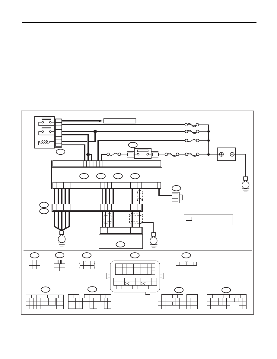
WIRING DIAGRAM:
EN-05681
5
6
7
8
2
1
9
4
3
10
24
22 23
25
11 12 13 14 15
26 27
28
16 17
18 19 20 21
33 34
29
32
30 31
B135
B:
B134
A:
B137
B136
D:
C:
E
38
39
28
6
24
25
*
*
E2
B21
E57
4
6
1
2
3
5
D4
D5
A29
A19
D7
A5
D2
D1
D3
35
34
37
40
36
A28
C6
A18
B21
B72
E57
1 2 3 4 5 6 7 8 9 10 11
12 13 14 15 16 17 18 19 20 21 22
23 24 25
34 35
36 37 38 39 40 41
48 49
50 51 52 53 54
42 43
44 45
46 47
26 27 28 29 30 31 32 33
B122
1 2 3 4
5 6 7 8
1
2
3
4
5
6
B47
1
2
8 9
5
6
3
4
10 11 12
19 20 21
29 30
31
13 14 15 16
17
27
28
18
22 23 24 25 26
7
32 33 34 35
B136
C:
1
2
7
8 9
5
6
3
4
10 11 12
19 20 21
29
30 31
13 14 15 16 17
27
28
18
22 23
24 25
26
B137
D:
1 2 3 4 5 6
B122
*
B134
A:
4
5
6
7
8
2
1
9
3
10 11 12 13
16 17
26 27
28
18 19
20 21 22 23
34 35
29 30 31
25
14 15
24
33
32
B135
B:
SBF-6
MAIN SBF
SBF-7
B72
A7
B2
C23
B5
B19
No.12
B47
1
2
4
6
5
3
E
No.13
SBF-5
1
3
E
1
3
4 5 6
2
MAIN RELAY
TO OXYGEN SENSOR
ECM
IGNITION
SWITCH
BATTERY
ELECTRONIC THROTTLE
CONTROL
: TERMINAL No. OPTIONAL
ARRANGEMENT

EN(H4DOTC)(diag)-250
Diagnostic Procedure with Diagnostic Trouble Code (DTC)
ENGINE (DIAGNOSTICS)
CH:DTC P0638 THROTTLE ACTUATOR CONTROL RANGE/PERFORMANCE
(BANK 1)
NOTE:
For the diagnostic procedure, refer to DTC P2101. <Ref. to EN(H4DOTC)(diag)-318, DTC P2101 THROT-
TLE ACTUATOR CONTROL MOTOR CIRCUIT RANGE/PERFORMANCE, Diagnostic Procedure with Di-
agnostic Trouble Code (DTC).>
CI: DTC P0700 TRANSMISSION CONTROL SYSTEM (MIL REQUEST)
NOTE:
For the diagnostic procedure, refer to AT section. <Ref. to 5AT(diag)-2, Basic Diagnostic Procedure.>
CJ:DTC P0851 PARK/NEUTRAL SWITCH INPUT CIRCUIT LOW (AT MODEL)
NOTE:
For the diagnostic procedure, refer to AT section. <Ref. to 5AT(diag)-2, Basic Diagnostic Procedure.>
Step
Check
Yes
No
1
CHECK INPUT VOLTAGE OF ECM.
1) Turn the ignition switch to ON.
2) Measure the voltage between ECM and
chassis ground.
Connector & terminal
(B134) No. 7 (+) — Chassis ground (–):
(B135) No. 2 (+) — Chassis ground (–):
Is the voltage 10 — 13 V?
Go to step 2.
Repair the open or
ground short circuit
of power supply
circuit.
2
CHECK INPUT VOLTAGE OF ECM.
1) Start the engine.
2) Measure the voltage between ECM and
chassis ground.
Connector & terminal
(B134) No. 7 (+) — Chassis ground (–):
(B135) No. 2 (+) — Chassis ground (–):
Is the voltage 13 — 15 V?
Go to step 3.
Repair the open or
ground short circuit
of power supply
circuit.
3
CHECK HARNESS BETWEEN ECM AND
ELECTRONIC THROTTLE CONTROL.
1) Turn the ignition switch to OFF.
2) Disconnect the connectors from ECM and
electronic throttle control.
3) Measure the resistance of harness between
ECM and electronic throttle control connector.
Connector & terminal
(B134) No. 19 — (E57) No. 5:
(B134) No. 29 — (E57) No. 3:
Is the resistance less than 1
:? Go to step 4.
Repair the open
circuit of harness
between ECM and
electronic throttle
control connector.
4
CHECK ECM GROUND HARNESS.
1) Connect all connectors.
2) Turn the ignition switch to ON.
3) Measure the voltage between ECM and
chassis ground.
Connector & terminal
(B134) No. 5 (+) — Chassis ground (–):
(B137) No. 1 (+) — Chassis ground (–):
(B137) No. 2 (+) — Chassis ground (–):
(B137) No. 3 (+) — Chassis ground (–):
(B137) No. 7 (+) — Chassis ground (–):
Is the voltage less than 1 V?
Repair the poor
contact of ECM
connector.
Repair the follow-
ing item.
• Open circuit of
ground circuit
• Retightening of
engine ground ter-
minals
• Poor contact of
coupling connector
EN(H4DOTC)(diag)-251
Diagnostic Procedure with Diagnostic Trouble Code (DTC)
ENGINE (DIAGNOSTICS)
CK:DTC P0851 NEUTRAL SWITCH INPUT CIRCUIT LOW (MT MODEL)
DTC DETECTING CONDITION:
• Two consecutive driving cycles with fault
• GENERAL DESCRIPTION <Ref. to GD(H4DOTC)-163, DTC P0851 NEUTRAL SWITCH INPUT CIRCUIT
LOW (MT MODEL), Diagnostic Trouble Code (DTC) Detecting Criteria.>
TROUBLE SYMPTOM:
Improper idling
CAUTION:
After repair or replacement of faulty parts, perform Clear Memory Mode <Ref. to EN(H4DOTC)(diag)-
52, OPERATION, Clear Memory Mode.>, and Inspection Mode <Ref. to EN(H4DOTC)(diag)-43, PRO-
CEDURE, Inspection Mode.>.
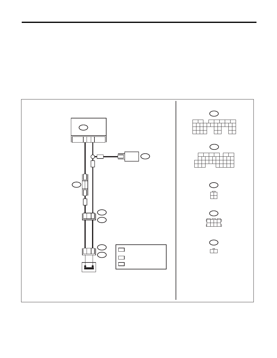
WIRING DIAGRAM:
EN-07063
ECM
31
B128
B128
T9
1
B55
B136
B122
11
TCM
B55
6
1
3 4
2
T12
NEUTRAL
POSITION
SWITCH
1 2 3 4
5 6 7 8
B122
: AT MODEL
*
*
*
3
T12
1
2
AT
: MT MODEL
MT
B136
5
6
7 8
2
1
9
4
3
10
24
22 23
25
11 12 13 14 15
26 27
28
16
17 18 19 20 21
33 34
29
32
30
31
35
1 2
MT
AT
MT
5
6
7
2
1
3
4
29
10 11 12 13 14 15
25
24
16
30
9
8
17 18 19
20
28
21 22 23
32
31
26 27
33
34 35
T2
: TERMINAL No. OPTIONAL
ARRANGEMENT

EN(H4DOTC)(diag)-252
Diagnostic Procedure with Diagnostic Trouble Code (DTC)
ENGINE (DIAGNOSTICS)
CL:DTC P0852 PARK/NEUTRAL SWITCH INPUT CIRCUIT HIGH (AT MODEL)
NOTE:
For the diagnostic procedure, refer to AT section. <Ref. to 5AT(diag)-2, Basic Diagnostic Procedure.>
Step
Check
Yes
No
1
CHECK INPUT SIGNAL OF ECM.
1) Turn the ignition switch to ON.
2) Place the shift lever in a position other than
neutral.
3) Measure the voltage between ECM and
chassis ground.
Connector & terminal
(B136) No. 31 (+) — Chassis ground (–):
Is the voltage 10 V or more?
Repair the poor
contact of ECM
connector.
Go to step 2.
2
CHECK HARNESS BETWEEN ECM AND
NEUTRAL POSITION SWITCH CONNEC-
TOR.
1) Turn the ignition switch to OFF.
2) Disconnect connectors from the ECM and
transmission harness connector (T9).
3) Measure the resistance between ECM and
chassis ground.
Connector & terminal
(B136) No. 31 — Chassis ground:
Is the resistance 1 M
: or
more?
Repair the short
circuit of transmis-
sion harness or
replace neutral
position switch.
<Ref. to 5MT-35,
Switches and Har-
ness.> <Ref. to
6MT-41, Neutral
Position Switch.>
Repair the ground
short circuit of har-
ness between
ECM and transmis-
sion harness con-
nector.
Нет комментариевНе стесняйтесь поделиться с нами вашим ценным мнением.
Текст