Subaru Legacy IV (2008 year). Service manual — part 358
EN(H4DOTC)(diag)-253
Diagnostic Procedure with Diagnostic Trouble Code (DTC)
ENGINE (DIAGNOSTICS)
CM:DTC P0852 NEUTRAL SWITCH INPUT CIRCUIT HIGH (MT MODEL)
DTC DETECTING CONDITION:
• Two consecutive driving cycles with fault
• GENERAL DESCRIPTION <Ref. to GD(H4DOTC)-165, DTC P0852 NEUTRAL SWITCH INPUT CIRCUIT
HIGH (MT MODEL), Diagnostic Trouble Code (DTC) Detecting Criteria.>
TROUBLE SYMPTOM:
Improper idling
CAUTION:
After repair or replacement of faulty parts, perform Clear Memory Mode <Ref. to EN(H4DOTC)(diag)-
52, OPERATION, Clear Memory Mode.>, and Inspection Mode <Ref. to EN(H4DOTC)(diag)-43, PRO-
CEDURE, Inspection Mode.>.
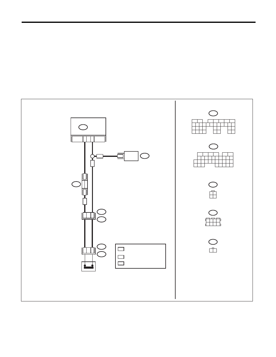
WIRING DIAGRAM:
EN-07063
ECM
31
B128
B128
T9
1
B55
B136
B122
11
TCM
B55
6
1
3 4
2
T12
NEUTRAL
POSITION
SWITCH
1 2 3 4
5 6 7 8
B122
: AT MODEL
*
*
*
3
T12
1
2
AT
: MT MODEL
MT
B136
5
6
7 8
2
1
9
4
3
10
24
22 23
25
11 12 13 14 15
26 27
28
16
17 18 19 20 21
33 34
29
32
30
31
35
1 2
MT
AT
MT
5
6
7
2
1
3
4
29
10 11 12 13 14 15
25
24
16
30
9
8
17 18 19
20
28
21 22 23
32
31
26 27
33
34 35
T2
: TERMINAL No. OPTIONAL
ARRANGEMENT

EN(H4DOTC)(diag)-254
Diagnostic Procedure with Diagnostic Trouble Code (DTC)
ENGINE (DIAGNOSTICS)
Step
Check
Yes
No
1
CHECK INPUT SIGNAL OF ECM.
1) Turn the ignition switch to ON.
2) Place the shift lever in neutral.
3) Measure the voltage between ECM and
chassis ground.
Connector & terminal
(B136) No. 31 (+) — Chassis ground (–):
Is the voltage less than 1 V?
Repair the poor
contact of ECM
connector.
Go to step 2.
2
CHECK HARNESS BETWEEN ECM AND
NEUTRAL POSITION SWITCH CONNEC-
TOR.
1) Turn the ignition switch to OFF.
2) Disconnect the connectors from ECM and
transmission harness connector (T9).
3) Measure the resistance of harness between
ECM and transmission harness connector.
Connector & terminal
(B136) No. 31 — (B128) No. 1:
Is the resistance less than 1
:? Go to step 3.
Repair the open
circuit in harness
between ECM and
transmission har-
ness connector.
3
CHECK HARNESS BETWEEN ECM AND
NEUTRAL POSITION SWITCH CONNEC-
TOR.
Measure the resistance of harness between
ECM and transmission harness connector.
Connector & terminal
(B128) No. 3 — (B136) No. 6:
Is the resistance less than 5
:? Go to step 4.
Repair the harness
and connector.
NOTE:
In this case, repair
the following item:
• Open circuit in
harness between
ECM and trans-
mission harness
connector
• Poor contact of
coupling connector
4
CHECK NEUTRAL POSITION SWITCH.
1) Place the shift lever in neutral.
2) Measure the resistance between transmis-
sion harness connector terminals.
Connector & terminal
(T9) No. 1 — No. 3:
Is the resistance less than 1
:? Repair the poor
contact of trans-
mission harness
connector.
Repair the open
circuit of transmis-
sion harness or
replace the neutral
position switch.
<Ref. to 5MT-35,
Switches and Har-
ness.> <Ref. to
6MT-41, Neutral
Position Switch.>
EN(H4DOTC)(diag)-255
Diagnostic Procedure with Diagnostic Trouble Code (DTC)
ENGINE (DIAGNOSTICS)
CN:DTC P1152 O2 SENSOR CIRCUIT RANGE/PERFORMANCE (LOW) (BANK1
SENSOR1)
DTC DETECTING CONDITION:
• Two consecutive driving cycles with fault
• GENERAL DESCRIPTION <Ref. to GD(H4DOTC)-166, DTC P1152 O2 SENSOR CIRCUIT RANGE/
PERFORMANCE (LOW) (BANK1 SENSOR1), Diagnostic Trouble Code (DTC) Detecting Criteria.>
CAUTION:
After repair or replacement of faulty parts, perform Clear Memory Mode <Ref. to EN(H4DOTC)(diag)-
52, OPERATION, Clear Memory Mode.>, and Inspection Mode <Ref. to EN(H4DOTC)(diag)-43, PRO-
CEDURE, Inspection Mode.>.
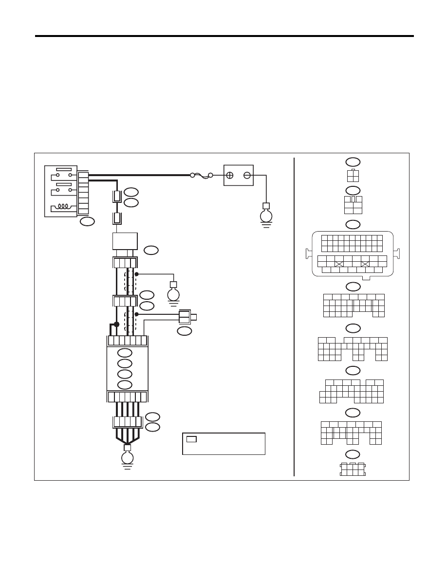
WIRING DIAGRAM:
EN-05669
SBF-5
B47
B21
E2
B21
E2
1
2
4
6
3
5
E
E
C2
C3
B8
B9
B1
B134
4
3
2
1
E79
3 4
1 2
3
4
1
2
5
6
B21
B47
E79
B134
5
6
7
8
2
1
9
4
3
10
24
22 23
25
11 12 13 14 15
26 27
28
16 17
18 19 20 21
33 34
29
32
30 31
A:
B135
B:
B136
C:
B137
D:
1 2 3 4
12 13 14 15
5 6 7 8
16 17 18 19
9 10 11
20 21 22
23 24 25 26 27 28 29 30 31 32 33
35
34
37
36
39
38
41
40
43
42
44
45
47
46
49
48
51
50
53
52
54
A:
D2
A5
D3
E2
B21
E
35
34
40
D7
36
D1
37
B138
*
*
*
16
10 11 12 13 14 15
25
24
30
9
8
7
17 18 19 20
28
21 22 23
29
32
31
1
2
3
4
5
6
27
26
33 34 35
B136
C:
B135
5
6
7
8
2
1
9
4
3
10
24
22 23
25
11 12 13 14 15
26 27
28
16 17 18 19
20 21
29 30 31
32 33
34 35
B137
5
6
7
8
2
1
9
4
3
10
22 23
11 12 13 14 15
24 25
26
16 17
18 19 20 21
27
28 29
30 31
B:
D:
1 2 3 4
5 6 7 8
B138
42
26
43
15
MAIN RELAY
BATTERY
FRONT
OXYGEN (A/F)
SENSOR
ECM
: TERMINAL No. OPTIONAL
ARRANGEMENT
AMONG 1, 2, 5 AND 6

EN(H4DOTC)(diag)-256
Diagnostic Procedure with Diagnostic Trouble Code (DTC)
ENGINE (DIAGNOSTICS)
Step
Check
Yes
No
1
CHECK FRONT OXYGEN (A/F) SENSOR
CONNECTOR AND COUPLING CONNEC-
TOR.
Has water entered the connec-
tor?
Completely
remove any water
inside.
Go to step 2.
2
CHECK HARNESS BETWEEN ECM AND
FRONT OXYGEN (A/F) SENSOR CONNEC-
TOR.
1) Turn the ignition switch to OFF.
2) Disconnect the connectors from ECM and
front oxygen (A/F) sensor.
3) Measure the resistance of harness between
ECM and front oxygen (A/F) sensor connector.
Connector & terminal
(B135) No. 9 — (E79) No. 1:
(B135) No. 8 — (E79) No. 3:
Is the resistance less than 1
:? Go to step 3.
Repair the harness
and connector.
NOTE:
In this case, repair
the following item:
• Open circuit in
harness between
ECM and front oxy-
gen (A/F) sensor
connector
• Poor contact of
coupling connector
3
CHECK POOR CONTACT.
Check for poor contact in the front oxygen (A/F)
sensor connector.
Is there poor contact in front
oxygen (A/F) sensor connec-
tor?
Repair the poor
contact of the front
oxygen (A/F) sen-
sor connector.
Replace the front
oxygen (A/F) sen-
sor. <Ref. to
FU(H4DOTC)-46,
Front Oxygen (A/F)
Sensor.>
Нет комментариевНе стесняйтесь поделиться с нами вашим ценным мнением.
Текст