Subaru Legacy IV (2008 year). Service manual — part 783
5MT-28
Manual Transmission Assembly
MANUAL TRANSMISSION AND DIFFERENTIAL
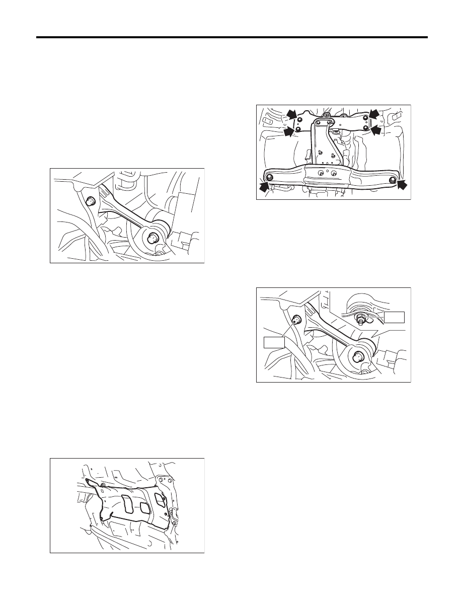
6) Install the front crossmember and rear cross-
member.
Tightening torque:
T1: 75 N·m (7.6 kgf-m, 55.3 ft-lb)
T2: 140 N·m (14.3 kgf-m, 103.3 ft-lb)
7) Take out the transmission jack.
8) Tighten the bolts and nuts which hold the lower
side of the transmission to the engine.
Tightening torque:
50 N·m (5.1 kgf-m, 36.9 ft-lb)
9) Connect the transmission to the engine.
(1) Install the starter. <Ref. to SC(H4SO)-6, IN-
STALLATION, Starter.>
(2) Tighten the bolts which hold the upper side
of the transmission to the engine.
Tightening torque:
50 N·m (5.1 kgf-m, 36.9 ft-lb)
10) Remove the ST.
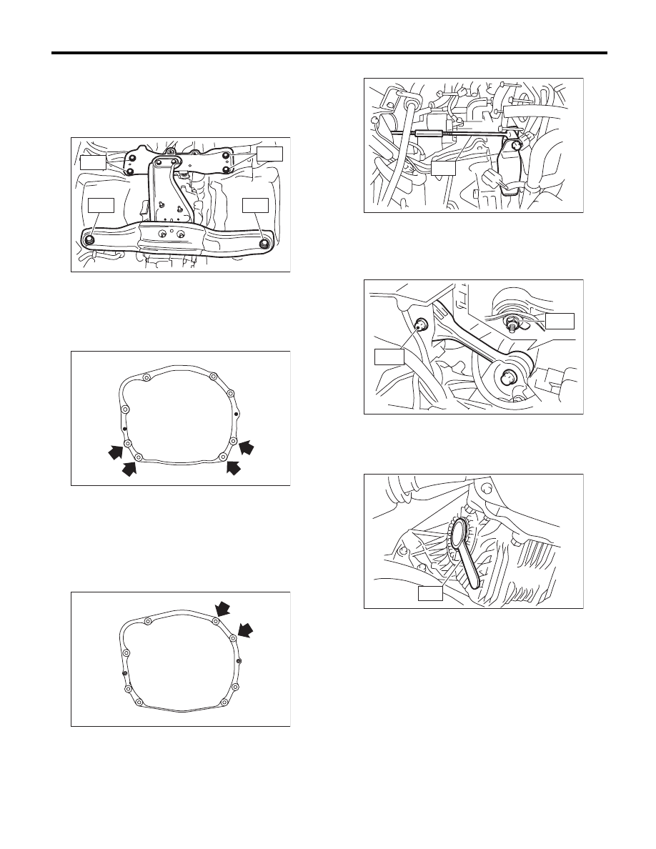
11) Install the pitching stopper.
Tightening torque:
T1: 50 N·m (5.1 kgf-m, 36.9 ft-lb)
T2: 58 N·m (5.9 kgf-m, 42.8 ft-lb)
12) Lift up the vehicle.
13) Install the front drive shaft into the transmis-
sion.
ST
28399SA010
OIL SEAL PROTECTOR
MT-01672
T 1
T 1
T 2
T 2
MT-00077
MT-01524
MT-01226
ST
MT-01557
T2
T1
AT-00110
ST
5MT-29
Manual Transmission Assembly
MANUAL TRANSMISSION AND DIFFERENTIAL
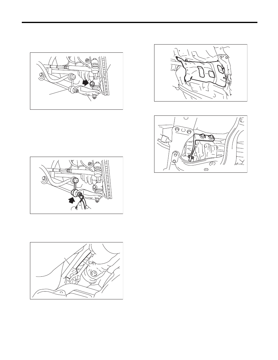
14) Insert the ball joints of the front arm into the
housing, then tighten the installing bolts.
Tightening torque:
50 N·m (5.1 kgf-m, 36.9 ft-lb)
15) Attach the stabilizer link to the front arm.
Tightening torque:
45 N·m (4.6 kgf-m, 33.2 ft-lb)
16) Attach the gear shift rod and stay.
(1) Attach the gear shift rod to the transmission.
Tightening torque:
18 N·m (1.8 kgf-m, 13.3 ft-lb)
(2) Attach the stay to the transmission.
Tightening torque:
18 N·m (1.8 kgf-m, 13.3 ft-lb)
17) Install the propeller shaft. <Ref. to DS-11, IN-
STALLATION, Propeller Shaft.>
18) Install the heat shield cover.
19) Install the hanger bracket on the right side of
the transmission.
20) Install the rear exhaust pipe and muffler.
• Non-turbo model
<Ref. to EX(H4SO)-8, INSTALLATION, Rear Ex-
haust Pipe.> <Ref. to EX(H4SO)-10, INSTALLA-
TION, Muffler.>
• Turbo model
<Ref. to EX(H4DOTC)-13, INSTALLATION, Rear
Exhaust Pipe.> <Ref. to EX(H4DOTC)-14, IN-
STALLATION, Muffler.>
21) Install the front and center exhaust pipe. (Non-
turbo model) <Ref. to EX(H4SO)-5, INSTALLA-
TION, Front Exhaust Pipe.> <Ref. to EX(H4SO)-7,
INSTALLATION, Center Exhaust Pipe.>
22) Install the center exhaust pipe. (Turbo model)
<Ref. to EX(H4DOTC)-9, INSTALLATION, Center
Exhaust Pipe.>
(A) Front arm
(B) Ball joint
(C) Stabilizer link
(A) Stay
(B) Gear shift rod
MT-00987
(A)
(C)
(B)
MT-00988
MT-00089
(A)
(B)
(B)
MT-01660
MT-00074
5MT-30
Manual Transmission Assembly
MANUAL TRANSMISSION AND DIFFERENTIAL
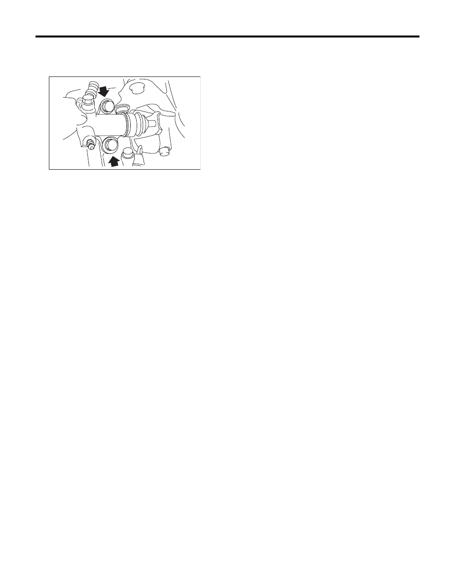
23) Install the operating cylinder.
Tightening torque:
37 N·m (3.8 kgf-m, 27.3 ft-lb)
24) Connect the following connectors.
(1) Transmission ground cable
Tightening torque:
13 N·m (1.3 kgf-m, 9.6 ft-lb)
(2) Neutral position switch connector
(3) Back-up light switch connector
25) Fill transmission gear oil through the transmis-
sion oil level gauge hole. <Ref. to 5MT-23, Trans-
mission Gear Oil.>
26) Install the air intake chamber stay. (Non-turbo
model)
Tightening torque:
16 N·m (1.6 kgf-m, 11.8 ft-lb)
27) Install the air intake chamber and intake boot.
(Non-turbo model) <Ref. to IN(H4SO)-7, INSTAL-
LATION, Air Intake Chamber.>
28) Install the intercooler. (Turbo model) <Ref. to
IN(H4DOTC)-13, INSTALLATION, Intercooler.>
29) Connect the ground cable to battery.
MT-01220
5MT-31
Transmission Mounting System
MANUAL TRANSMISSION AND DIFFERENTIAL
4. Transmission Mounting
System
A: REMOVAL
1. PITCHING STOPPER
1) Disconnect the ground cable from the battery.
2) Remove the air intake chamber and intake boot.
(Non-turbo model) <Ref. to IN(H4SO)-7, REMOV-
AL, Air Intake Chamber.>
3) Remove the intercooler. (Turbo model) <Ref. to
IN(H4DOTC)-12, REMOVAL, Intercooler.>
4) Remove the pitching stopper.
2. CROSSMEMBER AND CUSHION RUBBER
1) Disconnect the ground cable from the battery.
2) Lift up the vehicle.
3) Remove the front and center exhaust pipes.
(Non-turbo model) <Ref. to EX(H4SO)-4, REMOV-
AL, Front Exhaust Pipe.> <Ref. to EX(H4SO)-7,
REMOVAL, Center Exhaust Pipe.>
4) Remove the center exhaust pipe. (Turbo model)
<Ref. to EX(H4DOTC)-7, REMOVAL, Center Ex-
haust Pipe.>
5) Remove the rear exhaust pipe and muffler.
• Non-turbo model
<Ref. to EX(H4SO)-8, REMOVAL, Rear Exhaust
Pipe.> <Ref. to EX(H4SO)-10, REMOVAL, Muf-
fler.>
• Turbo model
<Ref. to EX(H4DOTC)-12, REMOVAL, Rear Ex-
haust Pipe.> <Ref. to EX(H4DOTC)-14, REMOV-
AL, Muffler.>
6) Remove the heat shield cover.
7) Set the transmission jack under the transmission
body.
CAUTION:
Always support the transmission case with a
transmission jack.
8) Remove the front and rear crossmembers.
9) Remove the transmission cushion rubber.
B: INSTALLATION
1. PITCHING STOPPER
1) Install the pitching stopper.
Tightening torque:
T1: 50 N·m (5.1 kgf-m, 36.9 ft-lb)
T2: 58 N·m (5.9 kgf-m, 42.8 ft-lb)
2) Install the air intake chamber and intake boot.
(Non-turbo model) <Ref. to IN(H4SO)-7, INSTAL-
LATION, Air Intake Chamber.>
3) Install the intercooler. (Turbo model)
<Ref. to IN(H4DOTC)-13, INSTALLATION, Inter-
cooler.>
4) Connect the ground cable to battery.
MT-01556
MT-01660
MT-01671
MT-01557
T2
T1
Нет комментариевНе стесняйтесь поделиться с нами вашим ценным мнением.
Текст