Subaru Legacy IV (2008 year). Service manual — part 784
5MT-32
Transmission Mounting System
MANUAL TRANSMISSION AND DIFFERENTIAL
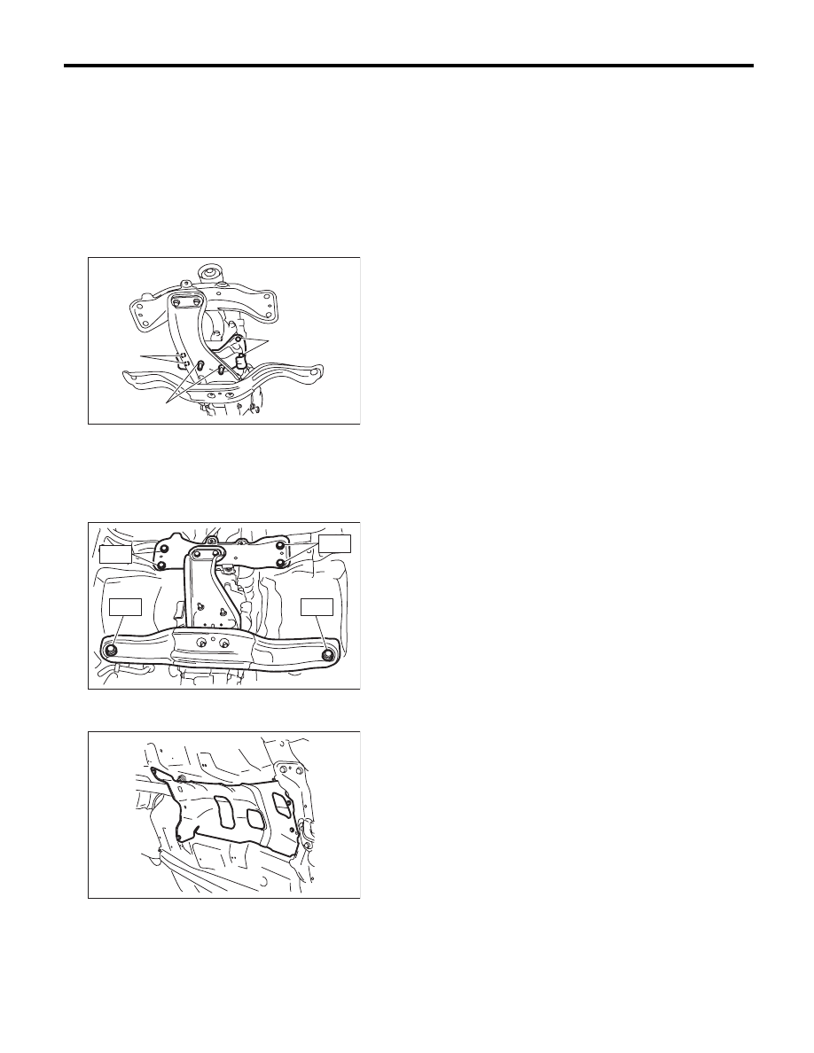
2. CROSSMEMBER AND CUSHION RUBBER
1) Install the transmission cushion rubber to the
transmission, and tighten the bolt (A).
2) Attach the transmission cushion rubber to the
center crossmember, and tighten nut (B).
Tightening torque:
Bolt (A)
35 N·m (3.6 kgf-m, 25.8 ft-lb)
Nut (B)
35 N·m (3.6 kgf-m, 25.8 ft-lb)
3) Install the front crossmember and rear cross-
member.
Tightening torque:
T1: 75 N·m (7.6 kgf-m, 55.3 ft-lb)
T2: 140 N·m (14.3 kgf-m, 103.3 ft-lb)
4) Remove the transmission jack.
5) Install the heat shield cover.
6) Install the front and center exhaust pipe. (Non-
turbo model) <Ref. to EX(H4SO)-5, INSTALLA-
TION, Front Exhaust Pipe.> <Ref. to EX(H4SO)-7,
INSTALLATION, Center Exhaust Pipe.>
7) Install the center exhaust pipe. (Turbo model)
<Ref. to EX(H4DOTC)-9, INSTALLATION, Center
Exhaust Pipe.>
8) Install the rear exhaust pipe and muffler.
• Non-turbo model
<Ref. to EX(H4SO)-8, INSTALLATION, Rear Ex-
haust Pipe.> <Ref. to EX(H4SO)-10, INSTALLA-
TION, Muffler.>
• Turbo model
<Ref. to EX(H4DOTC)-13, INSTALLATION, Rear
Exhaust Pipe.> <Ref. to EX(H4DOTC)-14, IN-
STALLATION, Muffler.>
9) Lower the vehicle.
10) Connect the ground cable to battery.
C: INSPECTION
Perform the following inspection procedures and
repair or replace faulty parts.
1. PITCHING STOPPER
Check the pitching stopper for bends or damage.
Check that the rubber is not stiff, cracked or other-
wise damaged.
2. CROSSMEMBER AND CUSHION RUBBER
Check crossmember for bends or damage. Check
that the cushion rubber is not stiff, cracked, or oth-
erwise damaged.
MT-01676
(A)
(A)
(B)
MT-01672
T 1
T 1
T 2
T 2
MT-01660
5MT-33
Oil Seal
MANUAL TRANSMISSION AND DIFFERENTIAL
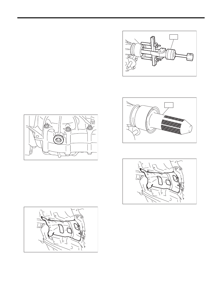
5. Oil Seal
A: INSPECTION
Check for leakage of gear oil from the oil seal. If
there is oil leakage, replace the oil seal with the
new part and check the propeller shaft.
B: REPLACEMENT
1) Clean the transmission exterior.
2) Using the TORX
®
bit T70, remove the drain
plug, and drain the transmission gear oil complete-
ly.
3) Using the TORX
®
bit T70, tighten the transmis-
sion gear oil drain plug.
NOTE:
Use a new gasket.
Tightening torque:
44 N·m (4.5 kgf-m, 32.5 ft-lb) (Aluminum gas-
ket)
70 N·m (7.1 kgf-m, 51.6 ft-lb) (Copper gasket)
4) Remove the rear exhaust pipe and muffler.
• Non-turbo model
<Ref. to EX(H4SO)-8, REMOVAL, Rear Exhaust
Pipe.> <Ref. to EX(H4SO)-10, REMOVAL, Muf-
fler.>
• Turbo model
<Ref. to EX(H4DOTC)-12, REMOVAL, Rear Ex-
haust Pipe.> <Ref. to EX(H4DOTC)-14, REMOV-
AL, Muffler.>
5) Remove the heat shield cover.
6) Remove the propeller shaft. <Ref. to DS-10, RE-
MOVAL, Propeller Shaft.>
7) Remove the oil seal using ST.
ST
398527700
PULLER ASSY
8) Using the ST, install the oil seal.
ST
498057300
INSTALLER
9) Install the propeller shaft. <Ref. to DS-11, IN-
STALLATION, Propeller Shaft.>
10) Install the heat shield cover.
11) Install the rear exhaust pipe and muffler.
• Non-turbo model
<Ref. to EX(H4SO)-8, INSTALLATION, Rear Ex-
haust Pipe.> <Ref. to EX(H4SO)-10, INSTALLA-
TION, Muffler.>
• Turbo model
<Ref. to EX(H4DOTC)-13, INSTALLATION, Rear
Exhaust Pipe.> <Ref. to EX(H4DOTC)-14, IN-
STALLATION, Muffler.>
12) Pour in the transmission gear oil and check the
oil level. <Ref. to 5MT-23, Transmission Gear Oil.>
MT-01548
MT-01660
(A) Oil seal
MT-00098
(A)
ST
MT-01299
ST
MT-01660
5MT-34
Differential Side Retainer Oil Seal
MANUAL TRANSMISSION AND DIFFERENTIAL
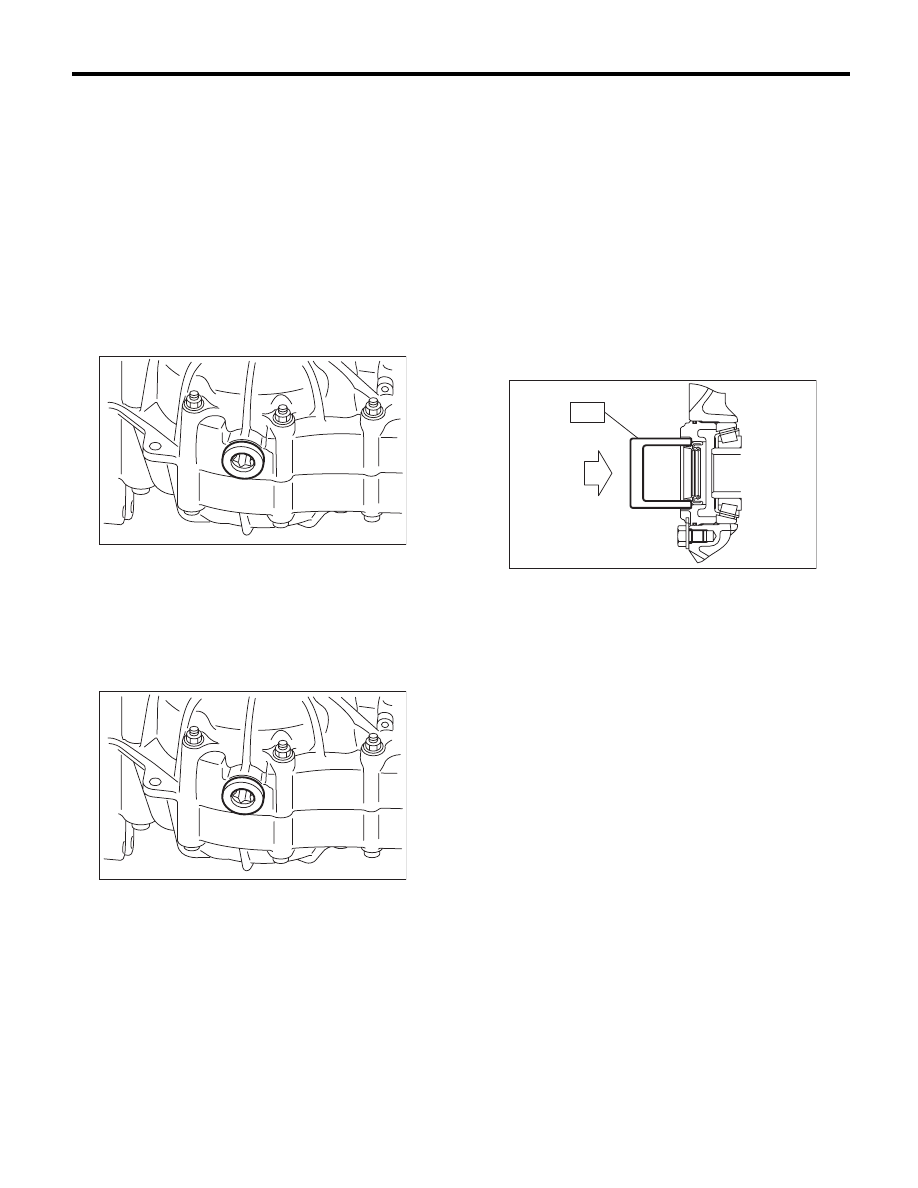
6. Differential Side Retainer Oil
Seal
A: INSPECTION
Check for leakage of gear oil from the differential
side retainer oil seal. If there is oil leakage, replace
the oil seal with the new part and check the drive
shaft.
B: REPLACEMENT
1) Lift up the vehicle.
2) Remove the differential gear oil drain plug using
TORX
®
bit T70, and drain the differential gear oil
completely.
3) Replace the gasket with a new part and tighten
the differential gear oil drain plug using the TORX
®
bit T70.
Tightening torque:
44 N·m (4.5 kgf-m, 32.5 ft-lb) (Aluminum gas-
ket)
70 N·m (7.1 kgf-m, 51.6 ft-lb) (Copper gasket)
4) Remove the front and center exhaust pipes.
(Non-turbo model) <Ref. to EX(H4SO)-4, REMOV-
AL, Front Exhaust Pipe.> <Ref. to EX(H4SO)-7,
REMOVAL, Center Exhaust Pipe.>
5) Remove the center exhaust pipe. (Turbo model)
<Ref. to EX(H4DOTC)-7, REMOVAL, Center Ex-
haust Pipe.>
6) Separate the front drive shaft from the transmis-
sion. <Ref. to DS-22, REMOVAL, Front Drive
Shaft.>
7) Remove the differential side retainer oil seal.
NOTE:
• Be sure to replace the differential side retainer oil
seal whenever the front drive shaft is removed from
the transmission.
• To remove the oil seal, use ST 398527700
PULLER ASSY. When removing the part by using
a flat tip screwdriver, be careful not to scratch the
differential side retainer.
8) Using the ST, install the differential side retainer
oil seal by lightly tapping with a plastic hammer.
ST
18675AA000
DIFFERENTIAL SIDE OIL
SEAL INSTALLER
NOTE:
Apply differential gear oil to the oil seal lips.
9) Install the front drive shaft. <Ref. to DS-22, IN-
STALLATION, Front Drive Shaft.>
10) Install the front and center exhaust pipe. (Non-
turbo model) <Ref. to EX(H4SO)-5, INSTALLA-
TION, Front Exhaust Pipe.> <Ref. to EX(H4SO)-7,
INSTALLATION, Center Exhaust Pipe.>
11) Install the center exhaust pipe. <Ref. to
EX(H4DOTC)-9, INSTALLATION, Center Exhaust
Pipe.>
12) Lower the vehicle.
13) Fill transmission gear oil through the oil level
gauge hole. <Ref. to 5MT-23, Transmission Gear
Oil.>
MT-01548
MT-01548
ST
MT-00103
5MT-35
Switches and Harness
MANUAL TRANSMISSION AND DIFFERENTIAL
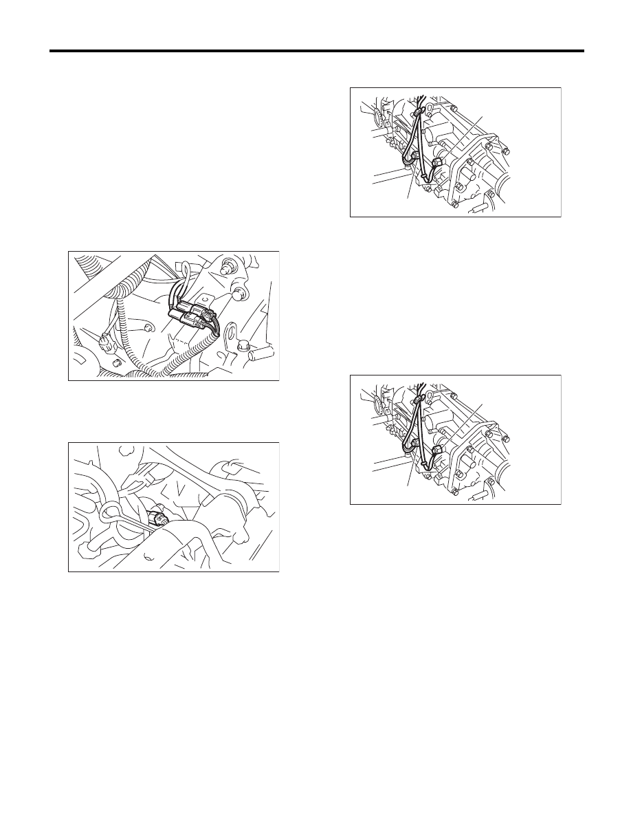
7. Switches and Harness
A: REMOVAL
1. BACK-UP LIGHT SWITCH & NEUTRAL
POSITION SWITCH
1) Disconnect the ground cable from the battery.
2) Remove the air intake chamber and intake boot.
(Non-turbo model) <Ref. to IN(H4SO)-7, REMOV-
AL, Air Intake Chamber.>
3) Remove the intercooler. (Turbo model) <Ref. to
IN(H4DOTC)-12, REMOVAL, Intercooler.>
4) Disconnect the connector back-up light switch &
neutral position switch.
• Non-turbo model
• Turbo model
5) Lift up the vehicle.
6) Remove the back-up light switch & neutral posi-
tion switch with the harness.
B: INSTALLATION
1. BACK-UP LIGHT SWITCH & NEUTRAL
POSITION SWITCH
1) Install the back-up light switch & neutral position
switch with the harness.
Tightening torque:
32.3 N·m (3.3 kgf-m, 23.8 ft-lb)
2) Connect the connectors of back-up light switch
and neutral position switch.
3) Install the air intake chamber and intake boot.
(Non-turbo model) <Ref. to IN(H4SO)-7, INSTAL-
LATION, Air Intake Chamber.>
4) Install the intercooler. (Turbo model)
<Ref. to IN(H4DOTC)-13, INSTALLATION, Inter-
cooler.>
5) Connect the ground cable to battery.
(A) Neutral position switch connector (Brown)
(B) Back-up light switch connector (Gray)
MT-00104
(A)
(B)
MT-00105
(A) Neutral position switch
(B) Back-up light switch
(A) Neutral position switch
(B) Back-up light switch
MT-00106
(A)
(B)
MT-00106
(A)
(B)
Нет комментариевНе стесняйтесь поделиться с нами вашим ценным мнением.
Текст