Subaru Legacy IV (2008 year). Service manual — part 1064
ET-13
Antenna
ENTERTAINMENT
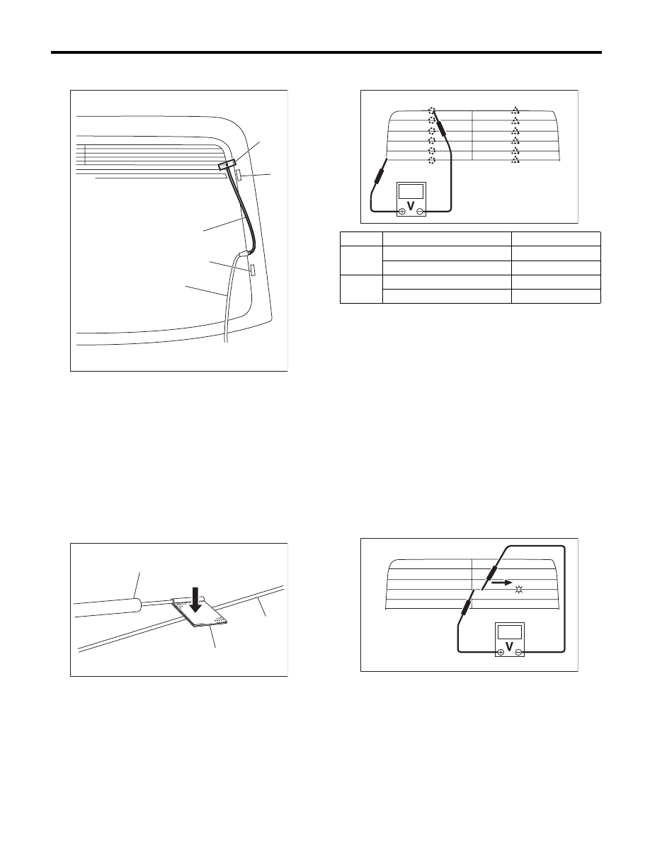
7) Fasten the another side of extension harness (B)
to end of printing pattern of grid with tape.
8) Connect the ground cable to battery.
9) Turn the ignition switch to ON.
10) Turn the rear defogger switch to ON.
11) Wrap a piece of aluminum foil around the tip of
tester probe and press foil against wire with your
finger.
12) Measure the voltage around an antenna wire
(a) and (b).
NOTE:
Measuring point (a)
• If the measured value is 6 V, heat wire is open
between antenna wire center and positive (+) ter-
minal of probe.
• If it is 0 V, the circuit is open between antenna
wire center and ground.
Measuring point (b)
• If the measured value is 12 V, heat wire is open
between antenna wire center and positive (+) ter-
minal of probe.
• If it is 6 V, the circuit is open between antenna
wire center and ground.
13) Fasten the voltmeter positive (+) side and neg-
ative (–) side to end of open harness of step 12).
14) Search a point the voltage changes from 0 V,
move the negative (–) probe along antenna wire.
15) Repair the antenna wire that determine the
place of the open circuit. <Ref. to ET-14, REPAIR,
Antenna.>
(1) Tape
(2) Antenna terminal
(3) Extension harness (B)
(4) Rear defogger terminal
(5) Rear defogger harness (ground side - black)
(A) Tester probe
(B) Aluminum foil
(C) Antenna wire
(1)
(2)
(3)
(4)
(5)
ET-00331
ET-00007
(B)
(C)
(A)
Measured voltage value
Criteria
(a)
Approx. 3V (standard value)
Normal
Approx. 6 V or 0 V
Open
(b)
Approx. 9V (standard value)
Normal
Approx. 12 V or 6 V
Open
(a)
(b)
ET-00332
ET-00333
ET-14
Antenna
ENTERTAINMENT
2. TYPE B
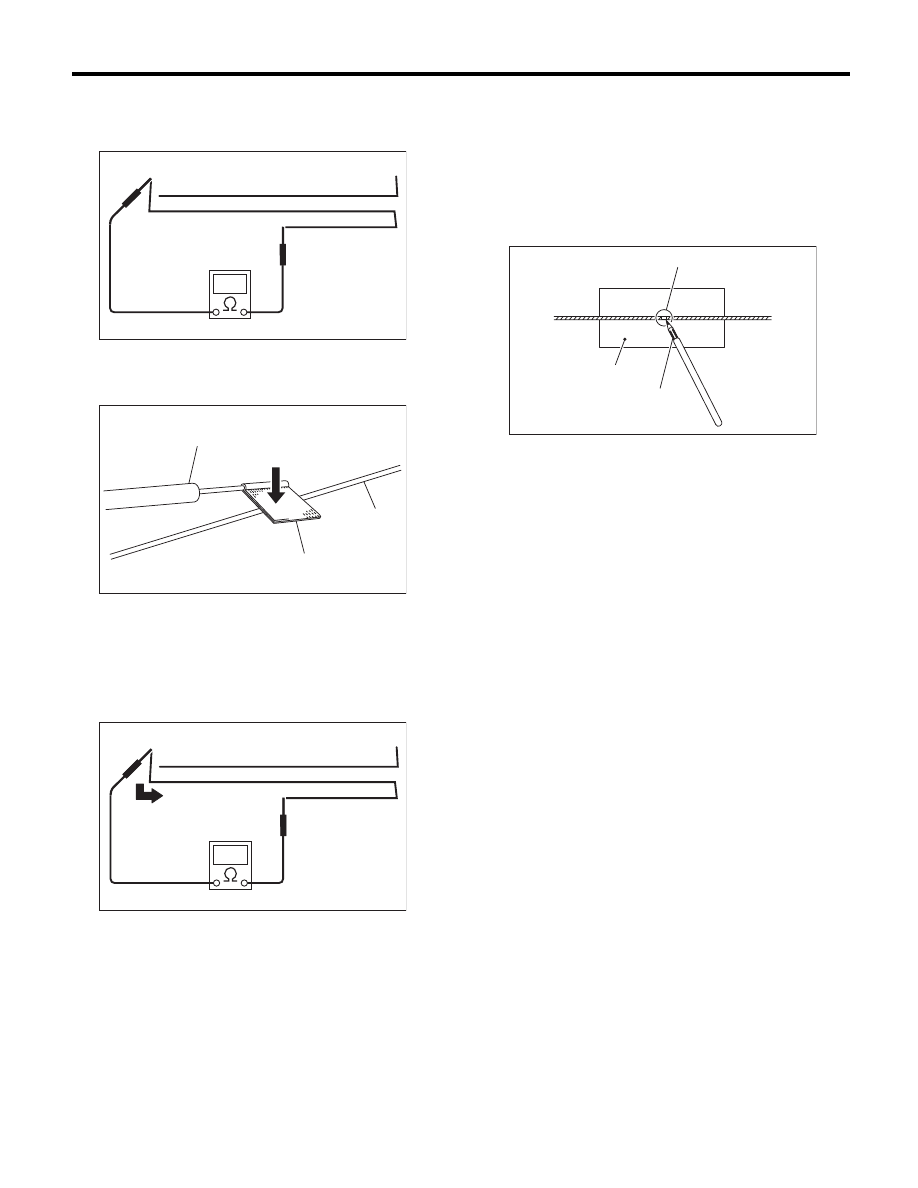
Measure the resistance between the antenna ter-
minal and each antenna wire.
1) Disconnect the ground cable from the battery.
2) Wrap a piece of aluminum foil around the tip of
probe and press foil against wire with your finger.
3) To locate the broken point, move the probe
along antenna wire.
NOTE:
If an antenna wire is OK, resistance will be less
than 20
:.
If an antenna wire is broken, resistance will be
more than 1 M
:.
4) Repair the antenna wire that determine the place
of the open circuit. <Ref. to ET-14, REPAIR, Anten-
na.>
B: REPAIR
1) Clean the external circumference of antenna
wire and around with alcohol or white gasoline.
2) Paste a thin masking film on the glass along bro-
ken wire.
3) Apply the conductive silver composition (DU-
PONT No. 4817) on the broken portion with a draw-
ing pen.
4) Dry out the deposited portion.
5) After repair has been completed, measure the
resistance in repaired wire.
(A) Tester probe
(B) Aluminum foil
(C) Antenna wire
ET-00327
ET-00007
(B)
(C)
(A)
ET-00328
(A) Broken portion
(B) Masking film
(C) Conductive silver composition
ET-00009
(B)
(C)
(A)
ET-15
Antenna Amplifier
ENTERTAINMENT
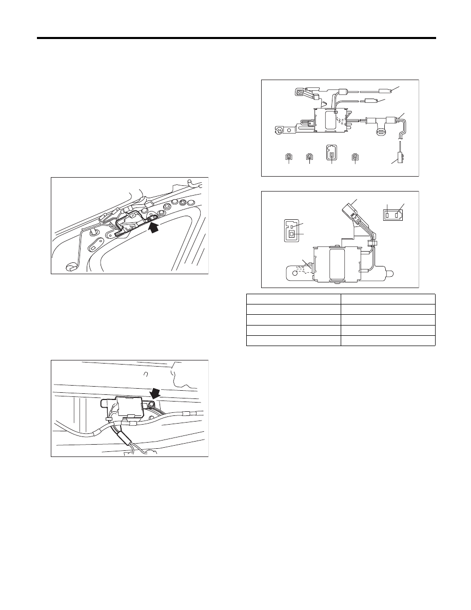
10.Antenna Amplifier
A: REMOVAL
1. SEDAN MODEL
1) Disconnect the ground cable from the battery.
2) Remove the rear quarter trim. <Ref. to EI-63,
SEDAN MODEL, REMOVAL, Rear Quarter Trim.>
3) Disconnect the harness connectors and termi-
nals.
4) Remove the curtain airbag module. <Ref. to AB-
18, REMOVAL, Curtain Airbag Module.>
5) Remove the screws and detach the antenna am-
plifier.
2. WAGON MODEL
1) Disconnect the ground cable from the battery.
2) Remove the rear gate trim. <Ref. to EI-68, RE-
MOVAL, Rear Gate Trim.>
3) Disconnect the harness connectors and termi-
nals.
4) Remove the screws and detach the antenna am-
plifier.
B: INSTALLATION
Install in the reverse order of removal.
C: INSPECTION
Measure the resistance of antenna amplifier.
• Sedan model
• Wagon model
ET-00088
ET-00089
Terminal No.
Standard
(1) — a and amplifier body
10 k
: or more
(1) — b and amplifier body
10 k
: or more
(2) — b and amplifier body
10 k
: or more
(3) — a and amplifier body
10 k
: or more
ET-00090
(3)
(2)
(2)-b
(1)-a
(1)-b
(3)-a
(1)-a
(1)-b
ET-00091
(3)-a
(2)-b
(1)-a
(1)-b
(1)
(2),(3)
ET-16
Noise Suppressor
ENTERTAINMENT
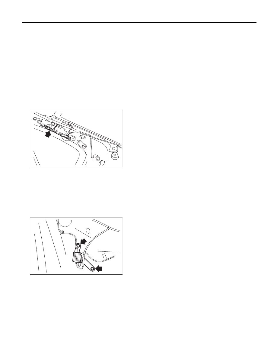
11.Noise Suppressor
A: REMOVAL
1. SEDAN MODEL
1) Disconnect the ground cable from the battery.
2) Remove the rear quarter trim. <Ref. to EI-63,
SEDAN MODEL, REMOVAL, Rear Quarter Trim.>
3) Remove the curtain airbag module. <Ref. to AB-
18, REMOVAL, Curtain Airbag Module.>
4) Disconnect harness connector from noise sup-
pressor.
5) Remove the harness clip.
6) Remove the screws and detach the noise sup-
pressor.
2. WAGON MODEL
1) Disconnect the ground cable from the battery.
2) Remove the rear gate trim. <Ref. to EI-68, RE-
MOVAL, Rear Gate Trim.>
3) Disconnect harness connector from noise sup-
pressor.
4) Remove the screws and detach the noise sup-
pressor.
B: INSTALLATION
Install in the reverse order of removal.
ET-00092
ET-00093
Нет комментариевНе стесняйтесь поделиться с нами вашим ценным мнением.
Текст