Subaru Legacy IV (2008 year). Service manual — part 661
CS-51
MT Gear Shift Lever
CONTROL SYSTEMS
2. 6MT MODEL
NOTE:
• Clean all the parts before assembly.
• Apply NIGTIGHT LYW No. 2 grease or the equiv-
alent to each part. <Ref. to CS-6, 6MT GEAR
SHIFT LEVER, COMPONENT, General Descrip-
tion.>
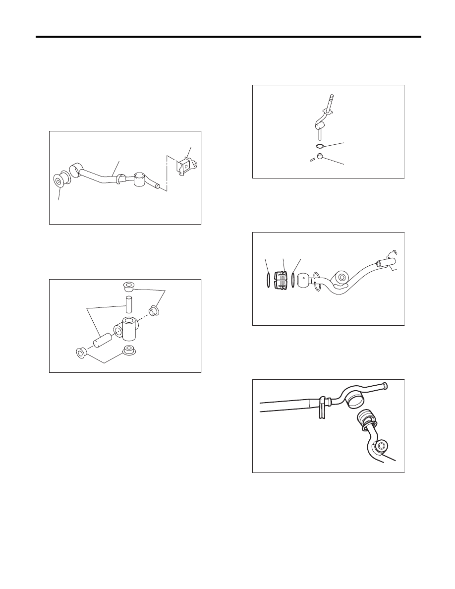
1) Mount the bushing and cushion rubber to the
stay.
2) Install the bushing and spacer to boss.
3) Install the snap ring to gear shift lever and install
the bushing.
NOTE:
Apply grease to the bushing.
4) Apply grease to the bushing and O-ring, and
then install to gear shift lever.
5) Apply sufficient grease to the boss, and then in-
stall the gear shift lever to the stay.
(A) Bushing
(B) Stay
(C) Cushion rubber
(A) Bushing
(B) Spacer
CS-00239
(B)
(C)
(A)
CS-00238
(B)
(A)
(A)
(A) Bushing
(B) Snap ring
(A) O-ring
(B) Bushing
CS-00237
(A)
(B)
CS-00236
(A)
(B)
(A)
CS-00235
CS-52
MT Gear Shift Lever
CONTROL SYSTEMS
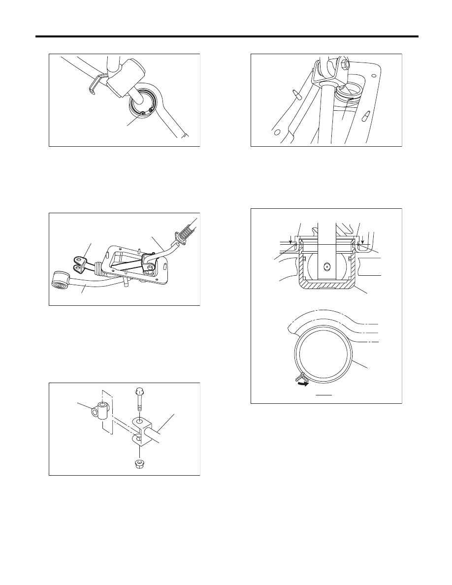
6) Install the washer and snap ring.
7) Insert the gear shift lever and rod into boot hole.
8) Install the rod.
Tightening torque:
12 N·m (1.2 kgf-m, 8.9 ft-lb)
9) Install the boss to the rod.
Tightening torque:
12 N·m (1.2 kgf-m, 8.9 ft-lb)
10) Install a new lock wire.
NOTE:
• Install the lock wire to the stay groove.
• Bend the extra wire to the same direction of lock
wire winding.
(A) Snap ring
(A) Rod
(B) Lever
(C) Stay
(A) Rod
(B) Boss
CS-00234
(A)
CS-00233
(C)
(A)
(B)
CS-00232
(B)
(A)
(A) Lock wire
(A) Inner boot
(B) Lock wire
(C) Stay
CS-00231
(A)
CS-00240
(A)
(A)
(B)
(B)
B
B
(B)
B - B
(C)
CS-53
MT Gear Shift Lever
CONTROL SYSTEMS
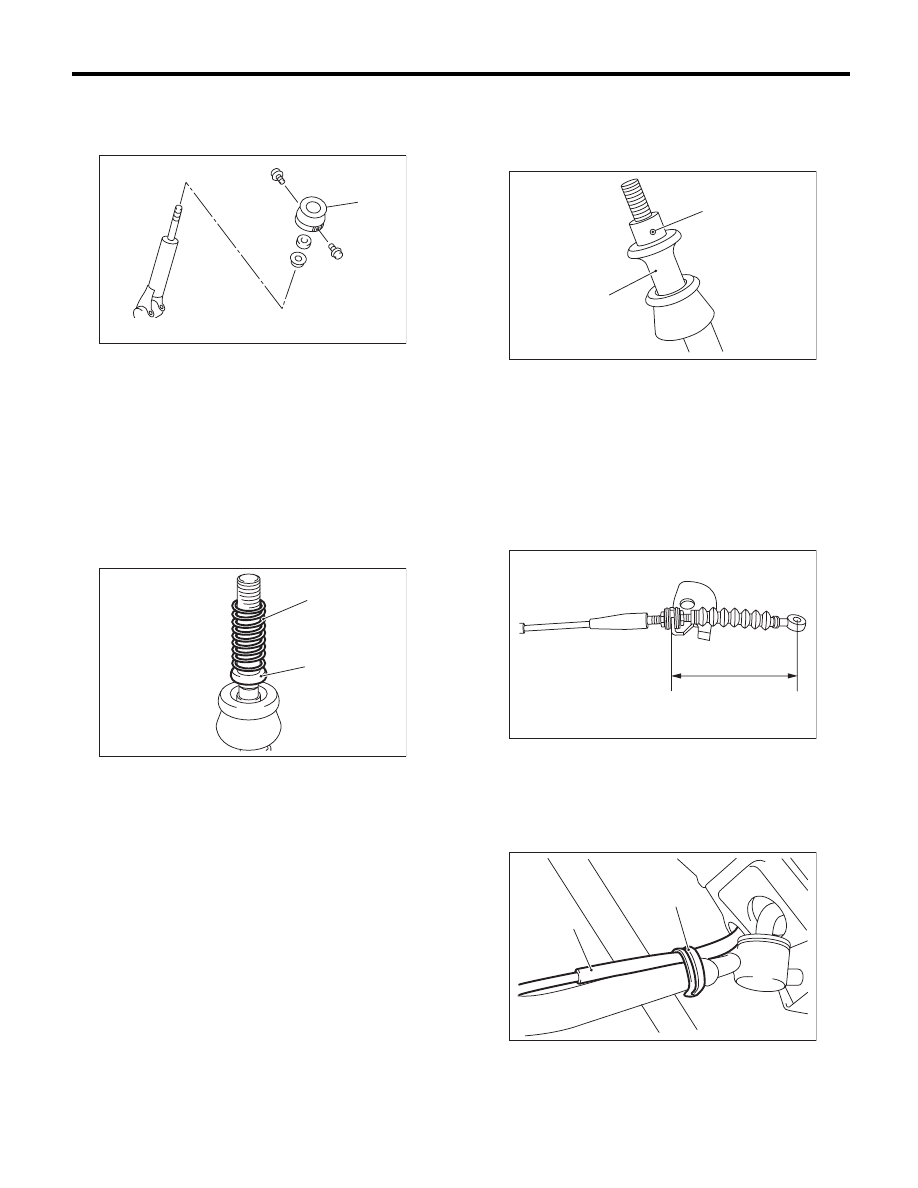
11) Install the holder.
Tightening torque:
1.3 N·m (0.1 kgf-m, 1.0 ft-lb)
12) Insert the reverse check cable into the boot
hole.
13) Insert the reverse check cable to the gear shift
assembly, and affix with a band clip.
NOTE:
• Cut the excess band clip.
• Make sure that the reverse check cable is insert-
ed into the gearshift lever with no gaps.
14) Attach the seat cushion and spring.
15) Use the spring pin to secure the end of the slid-
er and the reverse check cable.
NOTE:
Apply grease to the moving part of slider.
16) With the cable pulled (the slider is lowered), ad-
just the distance between the edge of cable plate
and the reverse check cable to 84 mm (3.31 in),
and tighten the lock nut.
Tightening torque:
6 N·m (0.6 kgf-m, 4.4 ft-lb)
17) Secure the reverse check cable to the stay clip.
NOTE:
Install the reverse check cable on top of the stay.
(A) Holder
(A) Spring
(B) Seat cushion
CS-00587
(A)
CS-00241
(A)
(B)
(A) Slider
(B) Spring pin
(A) 84 mm (3.31 in)
(A) Reverse check cable
(B) Clip
CS-00225
(A)
(B)
CS-00961
(A)
CS-00243
(A)
(B)
CS-54
MT Gear Shift Lever
CONTROL SYSTEMS
E: INSPECTION
1. 5MT MODEL
1) Check the parts (bushing, cushion rubber, spac-
er, boot, stay and rod, etc.) for deformation, dam-
age and wear. If necessary, correct or replace
faulty parts. Compare the removed parts with new
parts to judge if there are damages or not.
2) Check the swing torque of rod linked with the
gear shift lever.
If the torque exceeds the specifications, replace the
bushing or retighten nuts.
Swing torque:
3.7 N (0.38 kgf, 0.83 lbf) or less
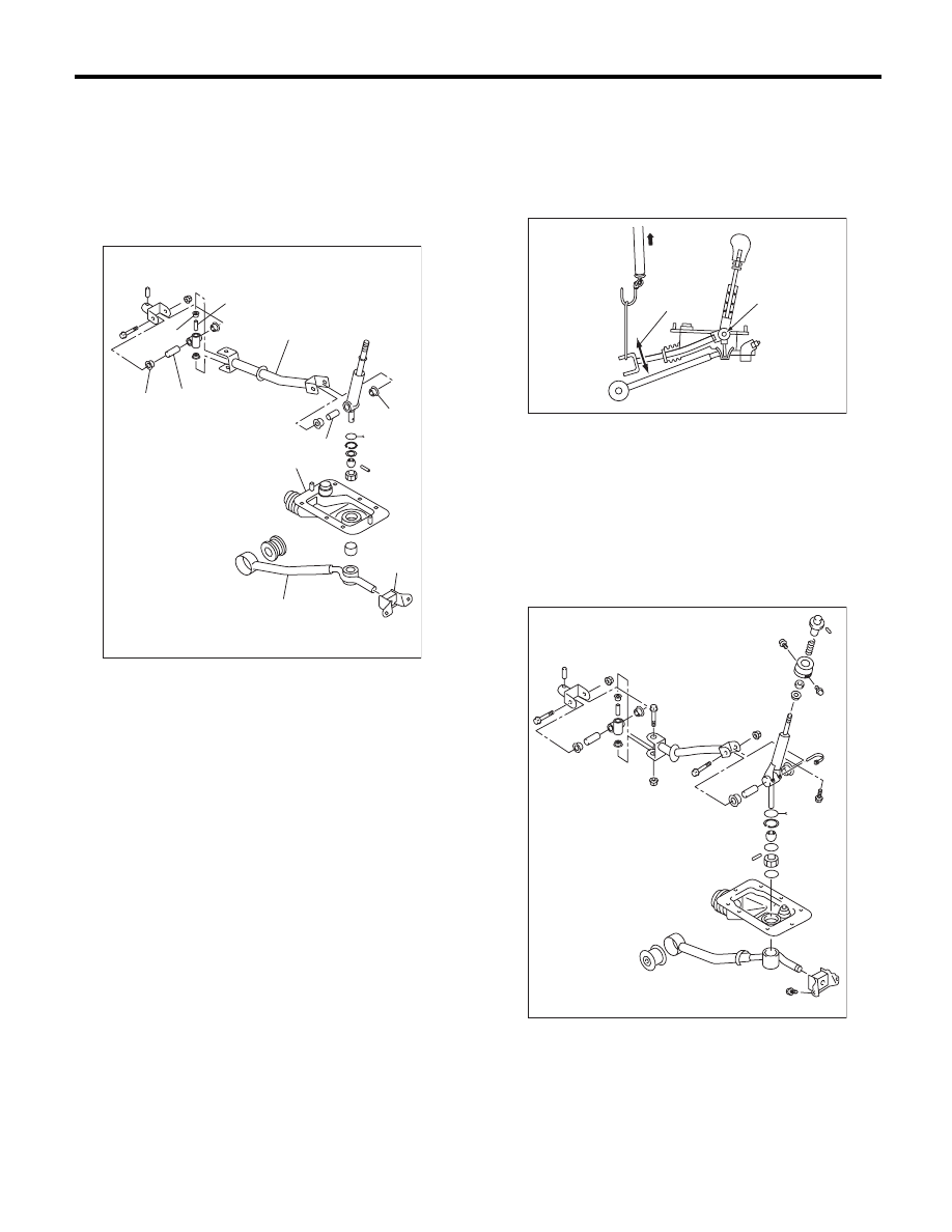
2. 6MT MODEL
Check the parts (bushing, cushion rubber, spacer,
boot, stay and rod, etc.) for deformation, damage
and wear. If necessary, correct or replace faulty
parts. Compare the removed parts with new parts
to judge if there are damages or not.
(A) Bushing
(B) Cushion rubber
(C) Spacer
(D) Boot
(E) Stay
(F) Rod
CS-00323
(C)
(D)
(A)
(F)
(A)
(E)
(C)
(A)
(B)
(C)
(A) Pivot
(B) Swing torque
CS-00116
(A)
(B)
CS-00586
Нет комментариевНе стесняйтесь поделиться с нами вашим ценным мнением.
Текст