Subaru Legacy IV (2008 year). Service manual — part 660
CS-47
MT Gear Shift Lever
CONTROL SYSTEMS
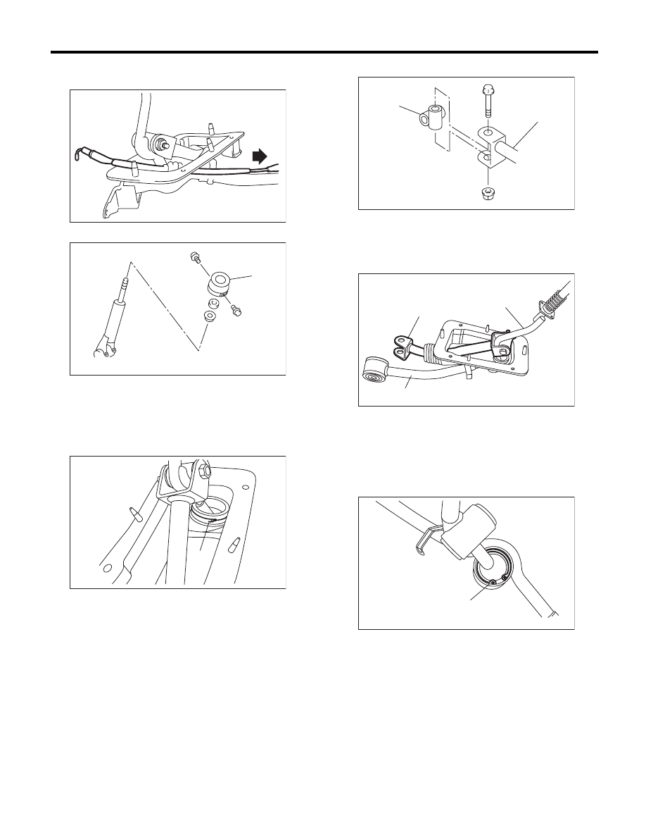
5) Remove the reverse check cable from the gear
shift assembly.
6) Remove the holder and spring.
7) Disassemble the lock wires.
NOTE:
Do not reuse the lock wire.
8) Remove the boss from the rod.
9) Remove the rod from lever.
10) Separate the rod and inner boot.
11) Remove the snap ring from the stay.
(A) Holder
(A) Lock wire
CS-00229
CS-00587
(A)
CS-00231
(A)
(A) Rod
(B) Boss
(A) Rod
(B) Lever
(C) Stay
(A) Snap ring
CS-00232
(B)
(A)
CS-00233
(C)
(A)
(B)
CS-00234
(A)
CS-48
MT Gear Shift Lever
CONTROL SYSTEMS
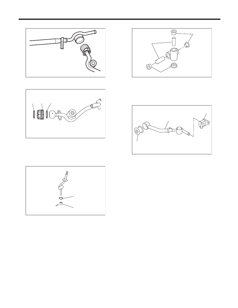
12) Separate the gear shift lever and the stay.
13) Remove the boot and bushing from gear shift
lever.
14) Remove the spring pin, and then remove the
bushing and snap ring.
15) Remove the bushing and spacer from the boss.
16) Remove the bushing and cushion rubber from
the stay.
(A) O-ring
(B) Bushing
(A) Bushing
(B) Snap ring
CS-00235
CS-00236
(A)
(B)
(A)
CS-00237
(A)
(B)
(A) Bushing
(B) Spacer
(A) Bushing
(B) Stay
(C) Cushion rubber
CS-00238
(B)
(A)
(A)
CS-00239
(B)
(C)
(A)
CS-49
MT Gear Shift Lever
CONTROL SYSTEMS
D: ASSEMBLY
1. 5MT MODEL
NOTE:
• Clean all the parts before assembly.
• Apply NIGTIGHT LYW No. 2 grease or the equiv-
alent to each part. <Ref. to CS-5, 5MT GEAR
SHIFT LEVER, COMPONENT, General Descrip-
tion.>
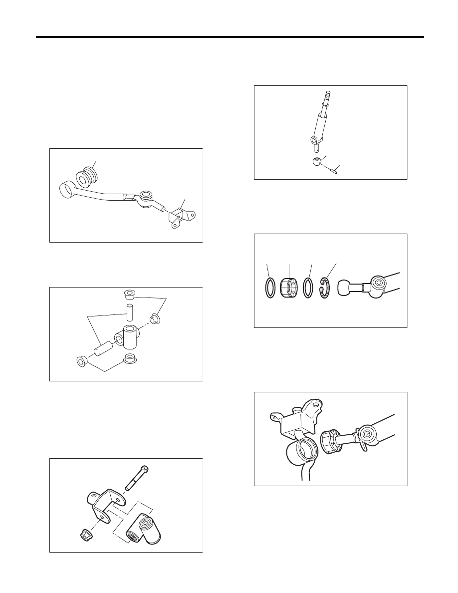
1) Mount the bushing and cushion rubber to the
stay.
2) Install the bushing and spacer to boss.
3) Using new self-locking nuts, install the boss to
the joint.
Tightening torque:
12 N·m (1.2 kgf-m, 8.9 ft-lb)
4) Install the snap ring to gear shift lever and install
the bushing.
NOTE:
Apply grease to the bushing.
5) Apply grease to the bushing and O-ring, and
then install to gear shift lever.
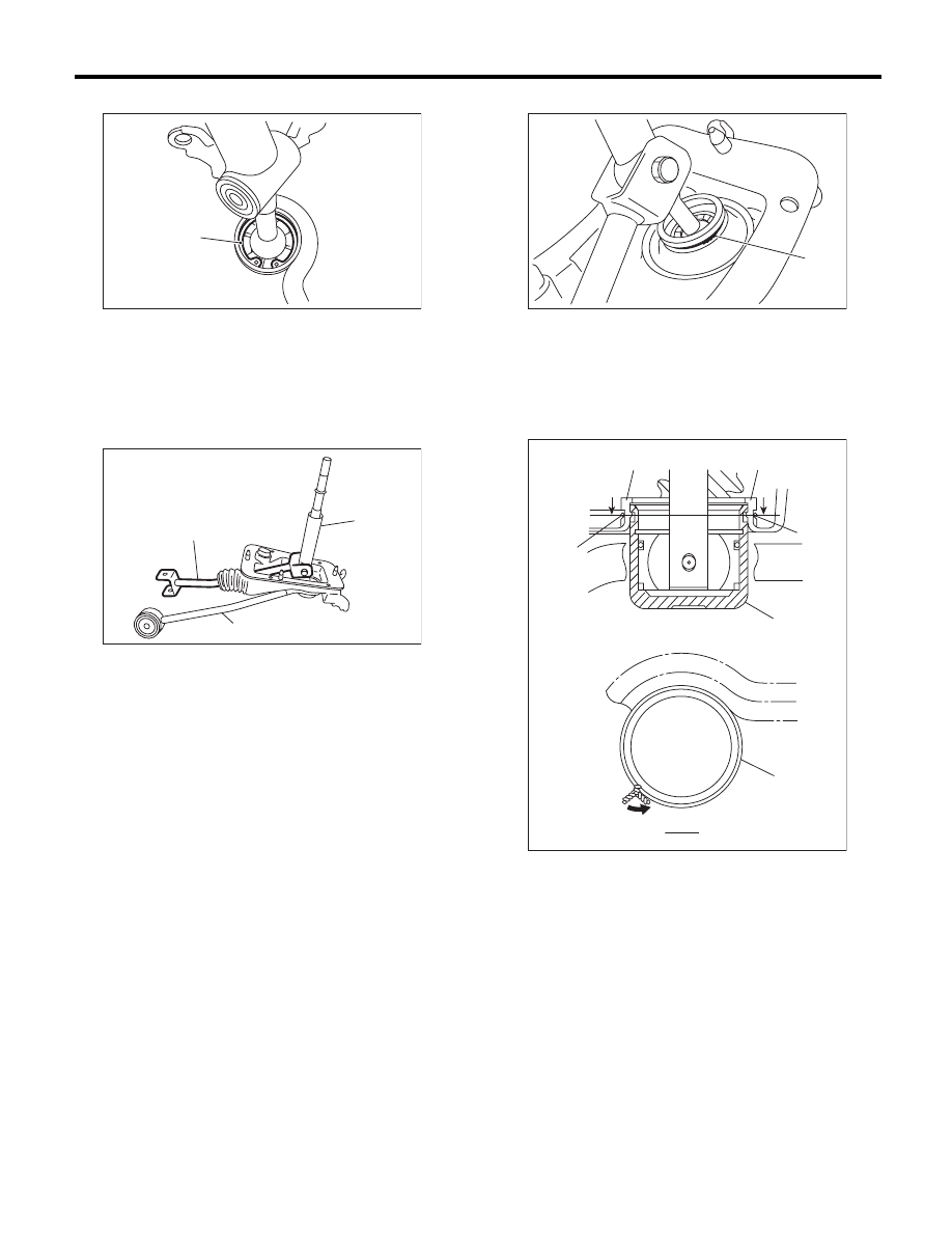
6) Apply sufficient grease into boss, and then install
the gear shift lever to the stay.
(A) Bushing
(B) Cushion rubber
(A) Bushing
(B) Spacer
CS-00061
(A)
(B)
CS-00238
(B)
(A)
(A)
CS-00322
(A) Spring pin
(B) Bushing
(A) O-ring
(B) Bushing
(C) Snap ring
CS-00060
(B)
(A)
CS-00320
(B)
(A)
(C)
(A)
CS-00319
CS-50
MT Gear Shift Lever
CONTROL SYSTEMS
7) Install the washer and snap ring.
8) Insert the gear shift lever and rod into boot hole.
9) Install the rod.
Tightening torque:
18 N·m (1.8 kgf-m, 13.3 ft-lb)
10) Install a new lock wire.
NOTE:
• Install the lock wire to the stay groove.
• Bend the extra wire to the same direction of lock
wire winding.
(A) Snap ring
(A) Rod
(B) Lever
(C) Stay
CS-00318
(A)
(A)
(B)
(C)
CS-00317
(A) Lock wire
(A) Inner boot
(B) Lock wire
(C) Stay
(A)
CS-00316
CS-00240
(A)
(A)
(B)
(B)
B
B
(B)
B - B
(C)
Нет комментариевНе стесняйтесь поделиться с нами вашим ценным мнением.
Текст