Subaru Legacy IV (2008 year). Service manual — part 573
EN(H6DO)(diag)-265
Diagnostic Procedure with Diagnostic Trouble Code (DTC)
ENGINE (DIAGNOSTICS)
CT:DTC P0507 IDLE AIR CONTROL SYSTEM RPM HIGHER THAN EXPECTED
DTC DETECTING CONDITION:
• Two consecutive driving cycles with fault
• GENERAL DESCRIPTION <Ref. to GD(H6DO)-149, DTC P0507 IDLE AIR CONTROL SYSTEM RPM
HIGHER THAN EXPECTED, Diagnostic Trouble Code (DTC) Detecting Criteria.>
TROUBLE SYMPTOM:
Engine keeps running at higher speed than specified idle speed.
CAUTION:
After repair or replacement of faulty parts, perform Clear Memory Mode <Ref. to EN(H6DO)(diag)-52,
OPERATION, Clear Memory Mode.>, and Inspection Mode <Ref. to EN(H6DO)(diag)-44, PROCEDURE,
Inspection Mode.>.
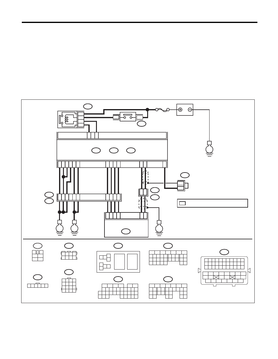
WIRING DIAGRAM:
1 2 3 4
5 6 7 8
9 10 11 12
13 14 15 16
B20
1 2 3 4 5 6
E57
1 2 3 4
5 6 7 8
B122
1 2
7 8
3
4
5
6
B362
36
52
34
35
37
E
E2
B21
E
A5
C21
C1
A29
19
E1
B20
A18
C6
A28
6
4
15
*
*
B122
16
E
38
39
20
D5
D4
A19
D7
D1
A3
D2
D3
3
E57
ELECTRONIC THROTTLE
CONTROL
2
1
5
B134
B362
5
7
6
A:
B137
B136
D:
C:
ECM
*
: TERMINAL No. OPTIONAL ARRANGEMENT
E
SBF-7
BATTERY
ELECTRONIC
THROTTLE
CONTROL RELAY
MAIN RELAY
8
6
4
B47
B47
3
4
1
2
5
6
EN-06873
16
10 11 12 13 14 15
25
24
30
9
8
7
17 18 19 20
28
21 22 23
29
32
31
1
2
3
4
5
6
27
26
33 34 35
B136
C:
5
6
7
8
2
1
9
4
3
10
22 23
11 12 13 14 15
24 25
26
16 17
18 19 20 21
27
28 29
30 31
B137
D:
5
6
7
8
2
1
9
4
3
10
24
22 23
25
11 12 13 14 15
26 27
28
16 17
18 19 20 21
33 34
29
32
30 31
B134
A:
B21
1 2 3 4 5 6 7 8 9 10 11
12 13 14 15 16 17 18 19 20 21 22
23 24 25 26 27 28 29 30 31 32 33
34
35
42
43
36
37
38
39
48
49
50
51
52
53
54
40
41
44
45
46
47

EN(H6DO)(diag)-266
Diagnostic Procedure with Diagnostic Trouble Code (DTC)
ENGINE (DIAGNOSTICS)
Step
Check
Yes
No
1
CHECK FOR ANY OTHER DTC ON DISPLAY. Is any other DTC displayed?
Check the appro-
priate DTC using
the “List of Diag-
nostic Trouble
Code (DTC)”.
<Ref. to
EN(H6DO)(diag)-
81, List of Diagnos-
tic Trouble Code
(DTC).>
Go to step 2.
2
CHECK AIR INTAKE SYSTEM.
1) Start and idle the engine.
2) Check the following items.
• Loose installation of intake manifold and
throttle body
• Cracks of intake manifold gasket and throttle
body gasket
• Disconnection of vacuum hoses
Is there any fault in air intake
system?
Repair air suction
and leaks.
Go to step 3.
3
CHECK ELECTRONIC THROTTLE CON-
TROL.
1) Turn the ignition switch to OFF.
2) Remove the electronic throttle control.
3) Check the electronic throttle control.
Are foreign matter found inside
electronic throttle control?
Remove foreign
matter from elec-
tronic throttle con-
trol.
Perform the diag-
nosis of DTC
P2101. <Ref. to
EN(H6DO)(diag)-
324, DTC P2101
THROTTLE
ACTUATOR CON-
TROL MOTOR
CIRCUIT RANGE/
PERFORMANCE,
Diagnostic Proce-
dure with Diagnos-
tic Trouble Code
(DTC).>
EN(H6DO)(diag)-267
Diagnostic Procedure with Diagnostic Trouble Code (DTC)
ENGINE (DIAGNOSTICS)
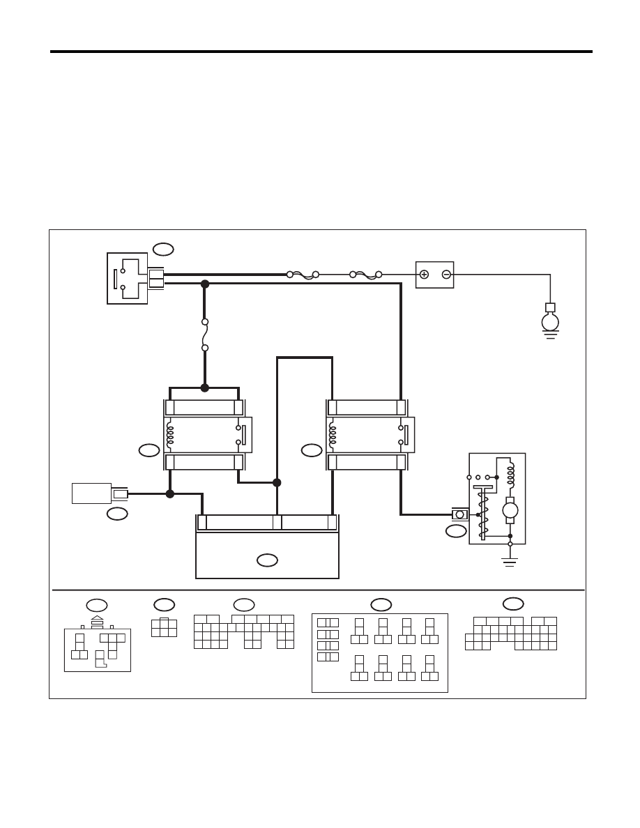
CU:DTC P0512 STARTER REQUEST CIRCUIT
DTC DETECTING CONDITION:
• Immediately at fault recognition
• GENERAL DESCRIPTION <Ref. to GD(H6DO)-150, DTC P0512 STARTER REQUEST CIRCUIT, Diag-
nostic Trouble Code (DTC) Detecting Criteria.>
TROUBLE SYMPTOM:
Failure of engine to start
CAUTION:
After repair or replacement of faulty parts, perform Clear Memory Mode <Ref. to EN(H6DO)(diag)-52,
OPERATION, Clear Memory Mode.>, and Inspection Mode <Ref. to EN(H6DO)(diag)-44, PROCEDURE,
Inspection Mode.>.
WIRING DIAGRAM:
16
10 11 12 13 14 15
25
24
30
9
8
7
17 18 19 20
28
21 22 23
29
32
31
1
2
3
4
5
6
27
26
33 34 35
32
31
20
No.21
B225
MAIN SBF
SBF-6
E
15
13
16
14
ECM
B136
TCM
B55
B72
B14
M
2
3
B225
B72
B136
10
11 12
13
14
15 16
17
18
19 20
21
22
23 24
25
26
27 28
29
30
31 32
33
34
35 36
39 40
37
38
1
2
9
3
4
5
6
7
8
1
3
4 5 6
2
B226
9
11
7
10
11
EN-05651
B226
B55
5
6
7
2
1
3
4
29
10 11 12 13 14 15
25
24
16
30
9
8
17 18 19
20
28
21 22 23
32
31
26 27
33
34 35
2
3 4
8
10
11
7
5
6
1
9
IGNITION
SWITCH
INHIBITOR
RELAY
STARTER
RELAY
STARTER MOTOR
BATTERY

EN(H6DO)(diag)-268
Diagnostic Procedure with Diagnostic Trouble Code (DTC)
ENGINE (DIAGNOSTICS)
CV:DTC P0600 SERIAL COMMUNICATION LINK
NOTE:
For the diagnostic procedure, refer to LAN section. <Ref. to LAN(diag)-2, Basic Diagnostic Procedure.>
Step
Check
Yes
No
1
CHECK FOR ANY OTHER DTC ON DISPLAY. Is any other DTC displayed?
Check the appro-
priate DTC using
the “List of Diag-
nostic Trouble
Code (DTC)”.
<Ref. to
EN(H6DO)(diag)-
81, List of Diagnos-
tic Trouble Code
(DTC).>
Go to step 2.
2
CHECK HARNESS BETWEEN ECM AND IG-
NITION SWITCH.
1) Turn the ignition switch to OFF.
2) Disconnect the connectors from ECM.
3) Turn the ignition switch to ON.
4) Measure the voltage between ECM and
chassis ground.
Connector & terminal
(B136) No. 32 (+) — Chassis ground (–):
Is the voltage 10 V or more?
Repair the short
circuit to power in
the harness
between the ECM
and ignition switch.
Repair the poor
contact of ECM
connector.
Нет комментариевНе стесняйтесь поделиться с нами вашим ценным мнением.
Текст