Subaru Legacy IV (2008 year). Service manual — part 574
EN(H6DO)(diag)-269
Diagnostic Procedure with Diagnostic Trouble Code (DTC)
ENGINE (DIAGNOSTICS)
CW:DTC P0604 INTERNAL CONTROL MODULE RANDOM ACCESS MEMORY
(RAM) ERROR
DTC DETECTING CONDITION:
• Immediately at fault recognition
• GENERAL DESCRIPTION <Ref. to GD(H6DO)-154, DTC P0604 INTERNAL CONTROL MODULE RAN-
DOM ACCESS MEMORY (RAM) ERROR, Diagnostic Trouble Code (DTC) Detecting Criteria.>
TROUBLE SYMPTOM:
• Engine does not start.
• Engine stalls.
CAUTION:
After repair or replacement of faulty parts, perform Clear Memory Mode <Ref. to EN(H6DO)(diag)-52,
OPERATION, Clear Memory Mode.>, and Inspection Mode <Ref. to EN(H6DO)(diag)-44, PROCEDURE,
Inspection Mode.>.
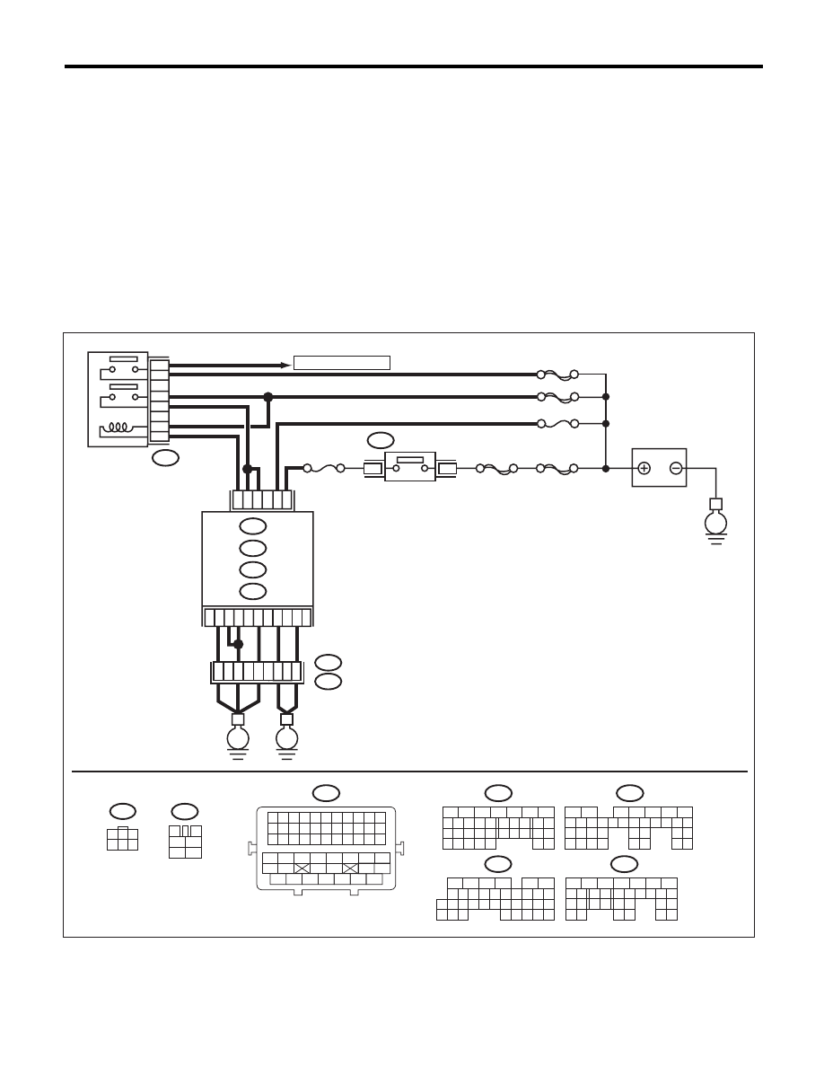
WIRING DIAGRAM:
SBF-6
MAIN SBF
SBF-7
B72
A7
B2
C23
A3
D2
D1
D7
B5
B19
No. 12
B47
E2
B21
1
2
4
6
5
3
ECM
E
E
3
1
B134
B135
A:
C: B136
D: B137
B:
35
34
52
3
4
1
2
5
6
B47
TO OXYGEN SENSOR
No. 13
A5
36
B72
1
3
4 5 6
2
E
SBF-5
D3
37
MAIN RELAY
BATTERY
IGNITION
SWITCH
EN-06864
B21
1 2 3 4 5 6 7 8 9 10 11
12 13 14 15 16 17 18 19 20 21 22
23 24 25 26 27 28 29 30 31 32 33
34
35
42
43
36
37
38
39
48
49
50
51
52
53
54
40
41
44
45
46
47
16
10 11 12 13
14 15
25
24
30
9
8
7
17 18 19 20
28
21 22 23
29
32
31
1
2
3
4
6
5
27
26
33 34 35
B136
C:
5
6
7
8
2
1
9
4
3
10
24
22 23
25
11 12 13 14 15
26
27
28
16
17
18 19 20 21
33
34
29
32
30 31
B134
A:
5
6
7
8
2
1
9
4
3
10
24
22 23
25
11 12 13 14 15
26 27
28
16 17 18 19
20 21
29 30 31
32 33
34 35
B135
B:
5
6
7
8
2
1
9
4
3
10
22 23
11 12 13 14 15
24 25
26
16 17
18 19 20 21
27
28 29
30 31
B137
D:

EN(H6DO)(diag)-270
Diagnostic Procedure with Diagnostic Trouble Code (DTC)
ENGINE (DIAGNOSTICS)
CX:DTC P0605 INTERNAL CONTROL MODULE READ ONLY MEMORY (ROM)
ERROR
NOTE:
For the diagnostic procedure, refer to DTC P0607. <Ref. to EN(H6DO)(diag)-271, DTC P0607 THROTTLE
CONTROL SYSTEM CIRCUIT RANGE/PERFORMANCE, Diagnostic Procedure with Diagnostic Trouble
Code (DTC).>
Step
Check
Yes
No
1
CHECK FOR ANY OTHER DTC ON DISPLAY. Is any other DTC displayed?
Check the appro-
priate DTC using
the “List of Diag-
nostic Trouble
Code (DTC)”.
<Ref. to
EN(H6DO)(diag)-
81, List of Diagnos-
tic Trouble Code
(DTC).>
Even if DTC is
detected, the cir-
cuit has returned to
a normal condition
at this time. Repro-
duce the failure,
and then perform
the diagnosis
again.
NOTE:
In this case, tem-
porary poor con-
tact of connector
may be the cause.
EN(H6DO)(diag)-271
Diagnostic Procedure with Diagnostic Trouble Code (DTC)
ENGINE (DIAGNOSTICS)
CY:DTC P0607 THROTTLE CONTROL SYSTEM CIRCUIT RANGE/PERFORMANCE
DTC DETECTING CONDITION:
• Immediately at fault recognition
• GENERAL DESCRIPTION <Ref. to GD(H6DO)-156, DTC P0607 THROTTLE CONTROL SYSTEM CIR-
CUIT RANGE/PERFORMANCE, Diagnostic Trouble Code (DTC) Detecting Criteria.>
TROUBLE SYMPTOM:
• Improper idling
• Poor driving performance
CAUTION:
After repair or replacement of faulty parts, perform Clear Memory Mode <Ref. to EN(H6DO)(diag)-52,
OPERATION, Clear Memory Mode.>, and Inspection Mode <Ref. to EN(H6DO)(diag)-44, PROCEDURE,
Inspection Mode.>.
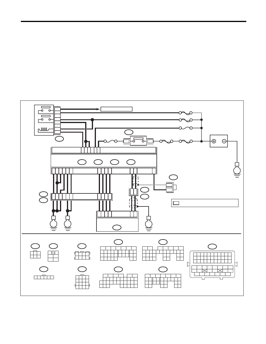
WIRING DIAGRAM:
B135
B:
B134
A:
B137
B136
D:
E1
B20
C:
E
E
38
39
20
19
16
15
*
*
E2
B21
E57
4
6
1
2
3
5
D4
D5
A29
A19
D1
D7
A5
D2
A3
D3
35
34
37
52
36
A28
C6
A18
ECM
B122
1 2 3 4
5 6 7 8
1
2
3
4
5
6
B47
ELECTRONIC THROTTLE
CONTROL
B20
1 2 3 4
5 6 7 8
9 10 11 12
13 14 15 16
E57
1 2 3 4 5 6
B122
*
: TERMINAL No. OPTIONAL ARRANGEMENT
E
SBF-6
MAIN SBF
SBF-7
B72
A7
B2
C23
B5
B19
No. 12
B47
1
2
4
6
5
3
E
3
1
No. 13
SBF-5
MAIN RELAY
BATTERY
IGNITION
SWITCH
EN-06880
B72
1
3
4 5 6
2
B21
1 2 3 4 5 6 7 8 9 10 11
12 13 14 15 16 17 18 19 20 21 22
23 24 25 26 27 28 29 30 31 32 33
34
35
42
43
36
37
38
39
48
49
50
51
52
53
54
40
41
44
45
46
47
16
10 11 12 13 14 15
25
24
30
9
8
7
17 18 19 20
28
21 22 23
29
32
31
1
2
3
4
5
6
27
26
33 34 35
B136
C:
5
6
7
8
2
1
9
4
3
10
22 23
11 12 13 14 15
24 25
26
16 17
18 19 20 21
27
28 29
30 31
B137
D:
5
6
7
8
2
1
9
4
3
10
24
22 23
25
11 12 13 14 15
26 27
28
16 17 18 19
20 21
29 30 31
32 33
34 35
B135
B:
5
6
7
8
2
1
9
4
3
10
24
22 23
25
11 12 13 14 15
26 27
28
16 17
18 19 20 21
33 34
29
32
30 31
B134
A:
TO OXYGEN SENSOR

EN(H6DO)(diag)-272
Diagnostic Procedure with Diagnostic Trouble Code (DTC)
ENGINE (DIAGNOSTICS)
CZ:DTC P0638 THROTTLE ACTUATOR CONTROL RANGE/PERFORMANCE
(BANK 1)
NOTE:
For the diagnostic procedure, refer to DTC P2101. <Ref. to EN(H6DO)(diag)-324, DTC P2101 THROTTLE
ACTUATOR CONTROL MOTOR CIRCUIT RANGE/PERFORMANCE, Diagnostic Procedure with Diagnos-
tic Trouble Code (DTC).>
DA:DTC P0700 TRANSMISSION CONTROL SYSTEM (MIL REQUEST)
NOTE:
For the diagnostic procedure, refer to AT section. <Ref. to 5AT(diag)-2, Basic Diagnostic Procedure.>
Step
Check
Yes
No
1
CHECK INPUT VOLTAGE OF ECM.
1) Turn the ignition switch to ON.
2) Measure the voltage between ECM and
chassis ground.
Connector & terminal
(B134) No. 7 (+) — Chassis ground (–):
(B135) No. 2 (+) — Chassis ground (–):
Is the voltage 10 — 13 V?
Go to step 2.
Repair the open or
ground short circuit
of power supply
circuit.
2
CHECK INPUT VOLTAGE OF ECM.
1) Start the engine.
2) Measure the voltage between ECM and
chassis ground.
Connector & terminal
(B134) No. 7 (+) — Chassis ground (–):
(B135) No. 2 (+) — Chassis ground (–):
Is the voltage 13 — 15 V?
Go to step 3.
Repair the open or
ground short circuit
of power supply
circuit.
3
CHECK HARNESS BETWEEN ECM AND
ELECTRONIC THROTTLE CONTROL.
1) Turn the ignition switch to OFF.
2) Disconnect the connectors from ECM and
electronic throttle control.
3) Measure the resistance of harness between
ECM and electronic throttle control connector.
Connector & terminal
(B134) No. 19 — (E57) No. 5:
(B134) No. 29 — (E57) No. 3:
Is the resistance less than 1
:? Go to step 4.
Repair the harness
and connector.
NOTE:
In this case, repair
the following item:
• Open circuit in
harness between
ECM and electron-
ic throttle control
connector
• Poor contact of
coupling connector
4
CHECK ECM GROUND HARNESS.
Measure the voltage between ECM and chassis
ground.
Connector & terminal
(B134) No. 3 (+) — Chassis ground (–):
(B134) No. 5 (+) — Chassis ground (–):
(B137) No. 1 (+) — Chassis ground (–):
(B137) No. 2 (+) — Chassis ground (–):
(B137) No. 3 (+) — Chassis ground (–):
(B137) No. 7 (+) — Chassis ground (–):
Is the voltage less than 1 V?
Repair the poor
contact of ECM
connector.
Repair the follow-
ing item.
• Open circuit of
ground circuit
• Retightening of
engine ground ter-
minals
• Poor contact of
coupling connector
Нет комментариевНе стесняйтесь поделиться с нами вашим ценным мнением.
Текст