Subaru Legacy IV (2008 year). Service manual — part 571
EN(H6DO)(diag)-257
Diagnostic Procedure with Diagnostic Trouble Code (DTC)
ENGINE (DIAGNOSTICS)
CL:DTC P0458 EVAPORATIVE EMISSION SYSTEM PURGE CONTROL VALVE
CIRCUIT LOW
DTC DETECTING CONDITION:
• Two consecutive driving cycles with fault
• GENERAL DESCRIPTION <Ref. to GD(H6DO)-134, DTC P0458 EVAPORATIVE EMISSION SYSTEM
PURGE CONTROL VALVE CIRCUIT LOW, Diagnostic Trouble Code (DTC) Detecting Criteria.>
TROUBLE SYMPTOM:
Improper idling
CAUTION:
After repair or replacement of faulty parts, perform Clear Memory Mode <Ref. to EN(H6DO)(diag)-52,
OPERATION, Clear Memory Mode.>, and Inspection Mode <Ref. to EN(H6DO)(diag)-44, PROCEDURE,
Inspection Mode.>.
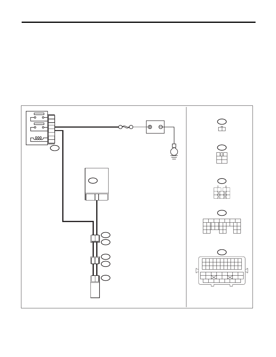
WIRING DIAGRAM:
E4
B47
B47
3
4
1
2
5
6
SBF-7
1
2
4
6
3
5
29
B21
E2
48
41
B137
ECM
2
1
E4
1 2
E
B137
5
6
7
8
2
1
9
4
3
10
22 23
11 12 13 14 15
24 25
26
16 17
18 19 20 21
27
28 29
30 31
10
2
E76
E77
E77
BATTERY
MAIN RELAY
PURGE CONTROL
SOLENOID VALVE
1 2
3 4
5
6
7
8
9
10
EN-06879
B21
1 2 3 4 5 6 7 8 9 10 11
12 13 14 15 16 17 18 19 20 21 22
23 24 25 26 27 28 29 30 31 32 33
34
35
42
43
36
37
38
39
48
49
50
51
52
53
54
40
41
44
45
46
47

EN(H6DO)(diag)-258
Diagnostic Procedure with Diagnostic Trouble Code (DTC)
ENGINE (DIAGNOSTICS)
Step
Check
Yes
No
1
CHECK OUTPUT SIGNAL OF ECM.
1) Turn the ignition switch to ON.
2) Measure the voltage between ECM and
chassis ground.
Connector & terminal
(B137) No. 29 (+) — Chassis ground (–):
Is the voltage 10 V or more?
Repair the poor
contact of ECM
connector.
Go to step 2.
2
CHECK IN HARNESS BETWEEN ECM AND
PURGE CONTROL SOLENOID VALVE.
1) Turn the ignition switch to OFF.
2) Disconnect the connectors from ECM and
purge control solenoid valve.
3) Measure the resistance between the purge
control solenoid valve connector and engine
ground.
Connector & terminal
(E4) No. 2 — Engine ground:
Is the resistance 1 M
: or
more?
Go to step 3.
Repair the ground
short circuit of har-
ness between
ECM and purge
control solenoid
valve connector.
3
CHECK HARNESS BETWEEN ECM AND
PURGE CONTROL SOLENOID VALVE.
Measure the resistance of harness between
ECM and purge control solenoid valve connec-
tor.
Connector & terminal
(B137) No. 29 — (E4) No. 2:
Is the resistance less than 1
:? Go to step 4.
Repair the harness
and connector.
NOTE:
In this case, repair
the following item:
• Open circuit in
harness between
ECM and purge
control solenoid
valve connector
• Poor contact of
coupling connector
4
CHECK PURGE CONTROL SOLENOID
VALVE.
1) Remove the purge control solenoid valve.
2) Measure the resistance between purge con-
trol solenoid valve terminals.
Terminals
No. 1 — No. 2:
Is the resistance between 10 —
100
:?
Go to step 5.
Replace the purge
control solenoid
valve. <Ref. to
EC(H6DO)-8,
Purge Control
Solenoid Valve.>
5
CHECK POWER SUPPLY TO PURGE CON-
TROL SOLENOID VALVE.
1) Turn the ignition switch to ON.
2) Measure the voltage between purge control
solenoid valve and engine ground.
Connector & terminal
(E4) No. 1 (+) — Engine ground (–):
Is the voltage 10 V or more?
Repair the poor
contact of purge
control solenoid
valve connector.
Repair the harness
and connector.
NOTE:
In this case, repair
the following item:
• Open circuit in
harness between
main relay and
purge control sole-
noid valve connec-
tor
• Poor contact of
coupling connector
• Poor contact of
main relay connec-
tor

EN(H6DO)(diag)-259
Diagnostic Procedure with Diagnostic Trouble Code (DTC)
ENGINE (DIAGNOSTICS)
CM:DTC P0459 EVAPORATIVE EMISSION SYSTEM PURGE CONTROL VALVE
CIRCUIT HIGH
DTC DETECTING CONDITION:
• Two consecutive driving cycles with fault
• GENERAL DESCRIPTION <Ref. to GD(H6DO)-136, DTC P0459 EVAPORATIVE EMISSION SYSTEM
PURGE CONTROL VALVE CIRCUIT HIGH, Diagnostic Trouble Code (DTC) Detecting Criteria.>
TROUBLE SYMPTOM:
Improper idling
CAUTION:
After repair or replacement of faulty parts, perform Clear Memory Mode <Ref. to EN(H6DO)(diag)-52,
OPERATION, Clear Memory Mode.>, and Inspection Mode <Ref. to EN(H6DO)(diag)-44, PROCEDURE,
Inspection Mode.>.
WIRING DIAGRAM:
E4
B47
B47
3
4
1
2
5
6
SBF-7
1
2
4
6
3
5
29
B21
E2
48
41
B137
ECM
2
1
E4
1 2
E
B137
5
6
7
8
2
1
9
4
3
10
22 23
11 12 13 14 15
24 25
26
16 17
18 19 20 21
27
28 29
30 31
10
2
E76
E77
E77
BATTERY
MAIN RELAY
PURGE CONTROL
SOLENOID VALVE
1 2
3 4
5
6
7
8
9
10
EN-06879
B21
1 2 3 4 5 6 7 8 9 10 11
12 13 14 15 16 17 18 19 20 21 22
23 24 25 26 27 28 29 30 31 32 33
34
35
42
43
36
37
38
39
48
49
50
51
52
53
54
40
41
44
45
46
47

EN(H6DO)(diag)-260
Diagnostic Procedure with Diagnostic Trouble Code (DTC)
ENGINE (DIAGNOSTICS)
Step
Check
Yes
No
1
CHECK HARNESS BETWEEN ECM AND
PURGE CONTROL SOLENOID VALVE.
1) Turn the ignition switch to OFF.
2) Disconnect the connectors from ECM and
purge control solenoid valve.
3) Turn the ignition switch to ON.
4) Measure the voltage between ECM and
chassis ground.
Connector & terminal
(B137) No. 29 (+) — Chassis ground (–):
Is the voltage 10 V or more?
Repair the short
circuit to power in
the harness
between ECM and
purge control sole-
noid valve connec-
tor.
Go to step 2.
2
CHECK PURGE CONTROL SOLENOID
VALVE.
1) Turn the ignition switch to OFF.
2) Measure the resistance between purge con-
trol solenoid valve terminals.
Terminals
No. 1 — No. 2:
Is the resistance less than 1
:? Replace the purge
control solenoid
valve. <Ref. to
EC(H6DO)-8,
Purge Control
Solenoid Valve.>
Repair the poor
contact of ECM
connector.
Нет комментариевНе стесняйтесь поделиться с нами вашим ценным мнением.
Текст