Subaru Legacy IV (2008 year). Service manual — part 994

AC(diag)-28
Diagnostic Procedure for Actuators
HVAC SYSTEM (AUTO A/C) (DIAGNOSTICS)
5
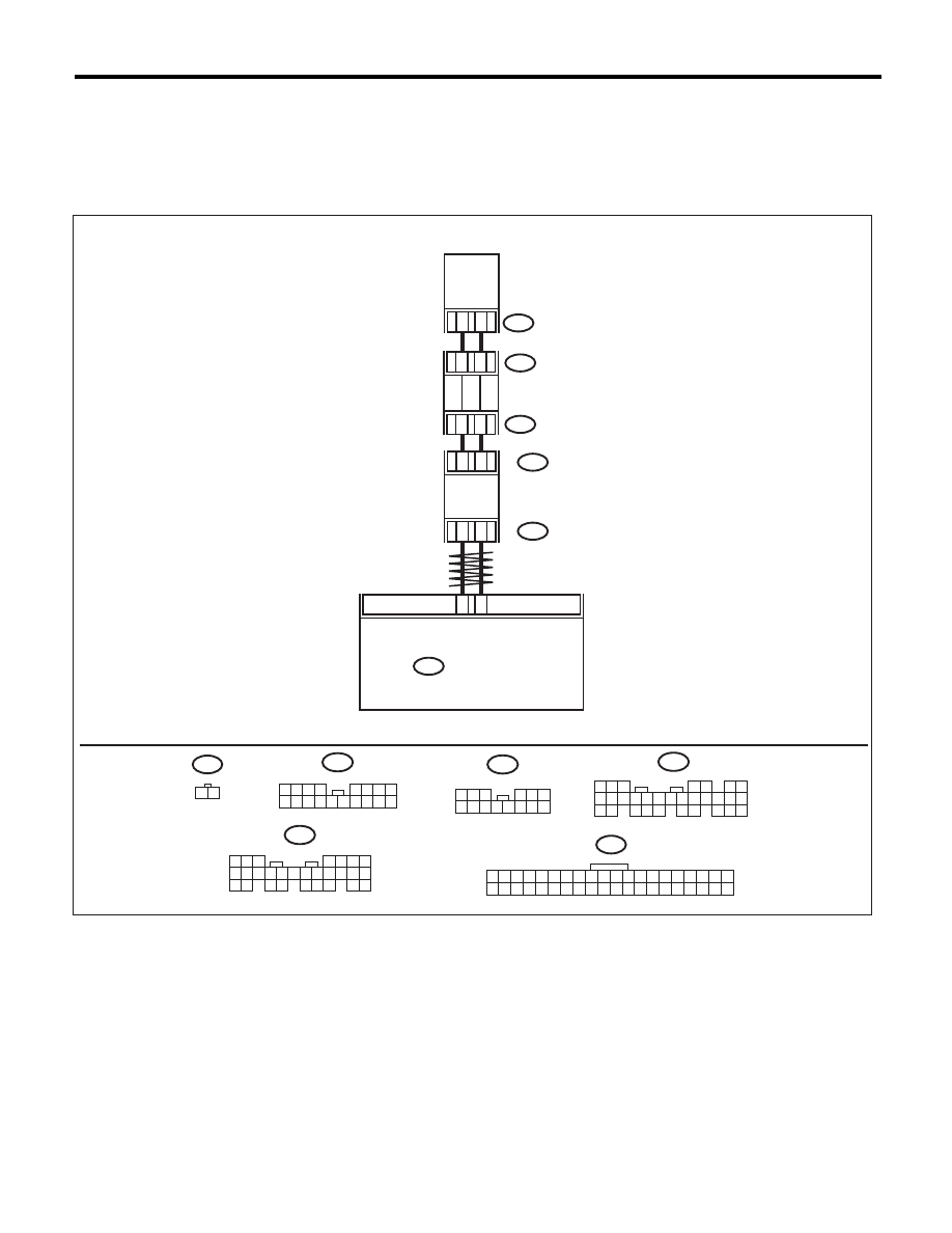
CHECK AIR MIX DOOR ACTUATOR POSI-
TION SWITCH SIGNAL.
1) Connect the connector of auto A/C control
module and air mix door actuator.
2) Turn the ignition switch and AUTO switch to
ON.
3) Check the voltage between auto A/C control
module connector terminals while changing the
setting temperature between maximum COOL
and maximum HOT.
Connector & terminal
Driver’s side
(B282) No. 24 (+) — (B282) No. 27 (–):
Passenger’s side
(B282) No. 4 (+) — (B282) No. 27 (–):
Does the voltage change
between 1 V (Max. HOT) and 4
V (Max. COOL)?
Go to step 6.
Replace the air mix
door actuator.
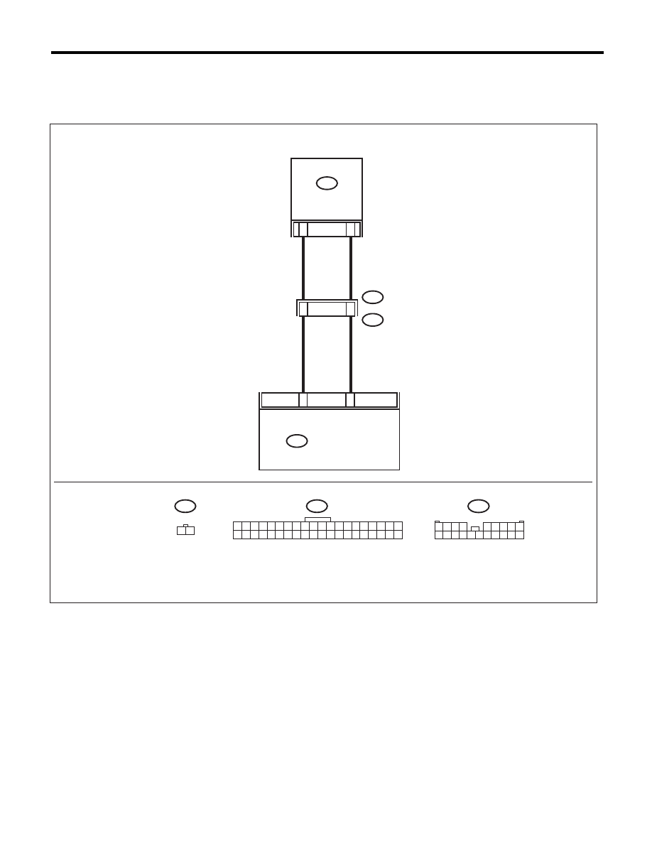
6
CHECK POOR CONTACT.
Check poor contact of auto A/C control module
and connector.
Is there poor contact in connec-
tor?
Repair the connec-
tor.
Replace the auto
A/C control mod-
ule.
Step
Check
Yes
No
AC(diag)-29
Diagnostic Procedure for Sensors
HVAC SYSTEM (AUTO A/C) (DIAGNOSTICS)
8. Diagnostic Procedure for Sensors
A: AMBIENT SENSOR
TROUBLE SYMPTOM:
Fan speed is not switched when the fan speed control dial is in AUTO position.
WIRING DIAGRAM:
B282
F78
10
9
B282
2
1
F78
1 2
10
11
14
13
B26
B25
C3
C10
F108
B361
B280
B281
B:
C:
5
4
6 7
8
2
1
9
3
10
22
23
11 12 13 14 15
24 25
26 27
16 17 18
28 29
19 20
21
30
B280
B281
B:
5 6 7
8
2
1
9
4
3
10
24
22 23
25
11 12 13 14 15
26
27 28
16 17 18 19
20 21
C:
1 2 3
4 5 6
7 8 9 10 11 12 13 14
B361
1 2 3
8
9 10
4
11 12 13 14 15 16
5 6 7
17 18
F108
AC-01652
1 2 3 4 5 6 7 8 9 10
21 22 23 24 25 26 27 28 29 30
11 12 13 14 15 16 17 18 19 20
31 32 33 34 35 36 37 38 39 40
AUTO A/C
CONTROL MODULE
AMBIENT
SENSOR
THROUGH
JOINT CONNECTOR
BODY INTEGRATED UNIT

AC(diag)-30
Diagnostic Procedure for Sensors
HVAC SYSTEM (AUTO A/C) (DIAGNOSTICS)
Step
Check
Yes
No
1
CHECK AMBIENT SENSOR.
1) Turn the ignition switch to OFF.
2) Disconnect the connector from ambient
sensor.
3) Measure the resistance between connector
terminals of ambient sensor.
Terminals
No. 1 — No. 2:
Is the resistance approximately
2.2 k
: at 25°C (77°F) ?
Go to step 2.
Replace the ambi-
ent sensor.
2
CHECK INPUT SIGNAL FOR AMBIENT SEN-
SOR.
1) Turn the ignition to ON.
2) Measure the voltage between connector
(F78) terminals.
Connector & terminal
(F78) No. 2 (+) — No. 1 (–):
Is the voltage approx. 5 V?
Go to step 6.
Go to step 3.
3
CHECK OUTPUT SIGNAL OF BODY INTE-
GRATED UNIT.
1) Turn the ignition switch to OFF.
2) Draw out the body integrated unit.
3) Disconnect the connector from ambient
sensor.
4) Turn the ignition switch to ON.
5) Measure the voltage between connector
terminals of body integrated unit.
Connector & terminal
(B281) No. 3 (+) — No. 10 (–):
Is the voltage approx. 5 V?
Go to step 4.
Go to step 6.
4
CHECK HARNESS CONNECTOR BETWEEN
BODY INTEGRATED UNIT AND AMBIENT
SENSOR.
1) Turn the ignition switch to OFF.
2) Disconnect the connector from body inte-
grated unit.
3) Measure the resistance of harness between
body integrated unit and ambient sensor.
Connector & terminal
(F78) No. 1 — (B281) No. 10:
Is the resistance less than 1
:? Go to step 5.
Repair the open
circuit of harness
between body inte-
grated unit and
ambient sensor.
5
CHECK HARNESS CONNECTOR BETWEEN
BODY INTEGRATED UNIT AND AMBIENT
SENSOR.
Measure the resistance of harness between
body integrated unit and ambient sensor.
Connector & terminal
(F78) No. 2 — (B281) No. 3:
Is the resistance less than 1
:? Go to step 6.
Repair the open
circuit of harness
between body inte-
grated unit and
ambient sensor.
6
CHECK DTC.
1) Connect the connectors of body integrated
unit and ambient sensor as originally con-
nected.
2) Read the DTC of body integrated unit using
Subaru Select Monitor.
Is DTC “U xxx” of CAN commu-
nication displayed?
Check the commu-
nication circuit.
<Ref. to
LAN(diag)-2, Basic
Diagnostic Proce-
dure.>
Go to step 7.
7
CHECK POOR CONTACT.
Check poor contact of auto A/C control module
connector.
Is there poor contact in connec-
tor?
Repair the connec-
tor.
Replace the auto
A/C control mod-
ule.
AC(diag)-31
Diagnostic Procedure for Sensors
HVAC SYSTEM (AUTO A/C) (DIAGNOSTICS)
B: IN-VEHICLE SENSOR
TROUBLE SYMPTOM:
Blower fan speed, outlet port and inlet port do not change after turning the AUTO switch to ON.
WIRING DIAGRAM:
B282
i55
B282
27
5
2
1
i3
B38
i55
1 2
12
11
1 2 3 4
5 6 7 8 9
10 11 12 13 14 15 16 17 18 19 20
B38
1 2 3 4 5 6 7 8 9 10
21 22 23 24 25 26 27 28 29 30
11 12 13 14 15 16 17 18 19 20
31 32 33 34 35 36 37 38 39 40
AC-01649
IN-VEHICLE SENSOR
AUTO A/C
CONTROL MODULE
Нет комментариевНе стесняйтесь поделиться с нами вашим ценным мнением.
Текст