Subaru Legacy IV (2008 year). Service manual — part 992

AC(diag)-20
Diagnostics for A/C System Malfunction
HVAC SYSTEM (AUTO A/C) (DIAGNOSTICS)
7
CHECK A/C ON SIGNAL.
1) Turn the ignition switch to OFF.
2) Connect the A/C relay and all disconnected
connectors.
3) Start the engine and turn the AUTO switch
to ON.
4) Turn the temperature control dial at maxi-
mum cool position.
5) Measure the voltage between auto A/C con-
trol module harness connector terminal and
chassis ground.
Connector & terminal
(B282) No. 15 (+) — Chassis ground (–):
Is the voltage 5.5 V or more?
Go to step 9.
Go to step 8.
8
CHECK HARNESS BETWEEN AUTO A/C
CONTROL MODULE AND ECM.
1) Turn the ignition switch to OFF.
2) Disconnect the harness connector of auto
A/C control module and ECM.
3) Measure the resistance of harness between
auto A/C control module connector and ECM
connector.
Connector & terminal
(B282) No. 15 — (B136) No. 24:
Is the resistance less than 1
:? Replace the auto
A/C control mod-
ule.
Repair the har-
ness.
9
CHECK MAGNET CLUTCH ON SIGNAL.
1) Stop the engine, and turn the AUTO switch
to OFF.
2) Turn the ignition switch to ON.
3) Measure the voltage between ECM connec-
tor terminal and chassis ground.
Connector & terminal
(B136) No. 9 (+) — Chassis ground (–):
Is the voltage 10 V or more?
Go to step 10.
Check for open or
short circuit in the
harness between
A/C relay and
ECM.
10
CHECK MAGNET CLUTCH ON SIGNAL.
1) Start the engine and turn the AUTO switch
to ON.
2) Turn the temperature control dial at maxi-
mum cool position.
3) Measure the voltage between ECM connec-
tor terminal and chassis ground.
Connector & terminal
(B136) No. 9 (+) — Chassis ground (–):
Is the voltage 0 V?
Go to step 11.
Replace the ECM.
11
CHECK POWER SUPPLY FOR MAGNET
CLUTCH.
1) Stop the engine, and turn the AUTO switch
to OFF.
2) Disconnect the harness connector of mag-
net clutch.
3) Start the engine and turn the AUTO switch
to ON.
4) Turn the temperature control dial at maxi-
mum cool position.
5) Measure the voltage between magnet
clutch harness connector terminal and chassis
ground.
Connector & terminal
(F24) No. 1 (+) — Chassis ground (–):
Is the voltage 10 V or more?
Go to step 12.
Check for open or
short circuit in the
harness between
A/C relay and mag-
net clutch.
Step
Check
Yes
No

AC(diag)-21
Diagnostics for A/C System Malfunction
HVAC SYSTEM (AUTO A/C) (DIAGNOSTICS)
12
CHECK HARNESS BETWEEN AUTO A/C
CONTROL MODULE AND ECM.
1) Stop the engine, and turn the AUTO switch
to OFF.
2) Measure the resistance between magnet
clutch harness connector terminal and chassis
ground.
Connector & terminal
(F24) No. 2 — Chassis ground:
Is the resistance less than 1
:? Inspect the com-
pressor. <Ref. to
AC-36, INSPEC-
TION, Compres-
sor.>
Repair the har-
ness.
Step
Check
Yes
No
AC(diag)-22
Diagnostic Procedure for Actuators
HVAC SYSTEM (AUTO A/C) (DIAGNOSTICS)
7. Diagnostic Procedure for Actuators
A: INTAKE DOOR ACTUATOR
TROUBLE SYMPTOM:
FRESH/RECIRC mode is not changed.
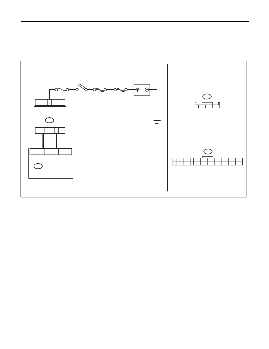
WIRING DIAGRAM:
AC-01646
B91
MAIN SBF
SBF-6
F/B No.22
7
3
1
B282
40
20
B91
B282
1 2 3 4 5 6 7
1 2 3 4 5 6 7 8 9 10 11 12 13 14 15 16 17 18 19 20
21 22 23 24 25 26 27 28 29 30 31 32 33 34 35 36 37 38 39 40
BATTERY
IGNITION
SWITCH
INTAKE DOOR
ACTUATOR
AUTO A/C
CONTROL MODULE

AC(diag)-23
Diagnostic Procedure for Actuators
HVAC SYSTEM (AUTO A/C) (DIAGNOSTICS)
Step
Check
Yes
No
1
CHECK POWER SUPPLY FOR INTAKE
DOOR ACTUATOR.
1) Turn the ignition switch to OFF.
2) Disconnect the intake door actuator con-
nector.
3) Turn the ignition switch to ON.
4) Measure the voltage between intake door
actuator connector and chassis ground.
Connector & terminal
(B91) No. 7 (+) — Chassis ground (–):
Is the voltage 7 V (at normal
temperature)?
Go to step 2.
Check for open or
short circuit in the
harness between
intake door actua-
tor and fuse.
2
CHECK HARNESS BETWEEN AUTO A/C
CONTROL MODULE AND INTAKE DOOR
ACTUATOR.
1) Turn the ignition switch to OFF.
2) Disconnect the auto A/C control module
connector.
3) Measure the resistance between intake
door actuator connector and auto A/C control
module connector.
Connector & terminal
(B282) No. 20 — (B91) No. 3:
(B282) No. 40 — (B91) No. 1:
Is the resistance less than 1
:? Go to step 3.
Repair the harness
between auto A/C
control module and
intake door actua-
tor.
3
CHECK OPERATION OF INTAKE DOOR AC-
TUATOR.
1) Connect the intake door actuator connector.
2) Ground the auto A/C control module con-
nector with a suitable wire.
3) Turn the ignition switch to ON, and check the
operation of intake door actuator.
Connector & terminal
(B282) No. 20 — Chassis ground:
Does the actuator move to the
FRESH side?
Go to step 4.
Replace the intake
door actuator.
4
CHECK OPERATION OF INTAKE DOOR AC-
TUATOR.
1) Turn the ignition switch to OFF.
2) Ground the auto A/C control module con-
nector with a suitable wire.
3) Turn the ignition switch to ON, and check the
operation of intake door actuator.
Connector & terminal
(B282) No. 40 — Chassis ground:
Does the actuator move to the
RECIRC side?
Replace the auto
A/C control mod-
ule.
Replace the intake
door actuator.
Нет комментариевНе стесняйтесь поделиться с нами вашим ценным мнением.
Текст