Subaru Legacy IV (2008 year). Service manual — part 995

AC(diag)-32
Diagnostic Procedure for Sensors
HVAC SYSTEM (AUTO A/C) (DIAGNOSTICS)
Step
Check
Yes
No
1
CHECK IN-VEHICLE SENSOR.
1) Turn the ignition switch to OFF.
2) Remove the driver’s side lower cover.
3) Disconnect the connector from in-vehicle
sensor.
4) Measure the resistance between connector
terminals of in-vehicle sensor.
Terminals
No. 1 — No. 2:
Is the resistance approximately
2.7 k
: at 20°C (68°F) ?
Go to step 2.
Replace the in-
vehicle sensor.
2
CHECK INPUT SIGNAL FOR IN-VEHICLE
SENSOR.
1) Turn the ignition switch to ON.
2) Measure the voltage between in-vehicle
sensor harness connector terminal and chassis
ground.
Connector & terminal
(i55) No. 2 (+) — No. 1 (–):
Is the voltage approx. 5 V?
Go to step 6.
Go to step 3.
3
CHECK AUTO A/C CONTROL MODULE
OUTPUT SIGNAL.
1) Turn the ignition switch to OFF.
2) Remove the auto A/C control module.
3) Turn the ignition switch to ON.
4) Measure the voltage between connector
terminals of auto A/C control module.
Connector & terminal
(B282) No. 5 (+) — (B282) No. 27 (–):
Is the voltage approx. 5 V?
Go to step 4.
Go to step 6.
4
CHECK HARNESS BETWEEN AUTO A/C
CONTROL MODULE AND IN-VEHICLE SEN-
SOR.
1) Turn the ignition switch to OFF.
2) Disconnect the connector from the auto A/C
control module.
3) Measure the resistance of harness between
auto A/C control module and in-vehicle sensor.
Connector & terminal
(i55) No. 2 — (B282) No. 5:
Is the resistance less than 1
:? Go to step 5.
Repair the harness
between auto A/C
control module and
in-vehicle sensor.
5
CHECK HARNESS BETWEEN AUTO A/C
CONTROL MODULE AND IN-VEHICLE SEN-
SOR.
Measure the resistance of harness between
auto A/C control module and in-vehicle sensor.
Connector & terminal
(i55) No. 1 — (B282) No. 27:
Is the resistance less than 1
:? Go to step 6.
Repair the harness
between auto A/C
control module and
in-vehicle sensor.
6
CHECK POOR CONTACT.
Check poor contact of auto A/C control module
connector.
Is there poor contact in connec-
tor?
Repair the connec-
tor.
Replace the auto
A/C control mod-
ule.
AC(diag)-33
Diagnostic Procedure for Sensors
HVAC SYSTEM (AUTO A/C) (DIAGNOSTICS)
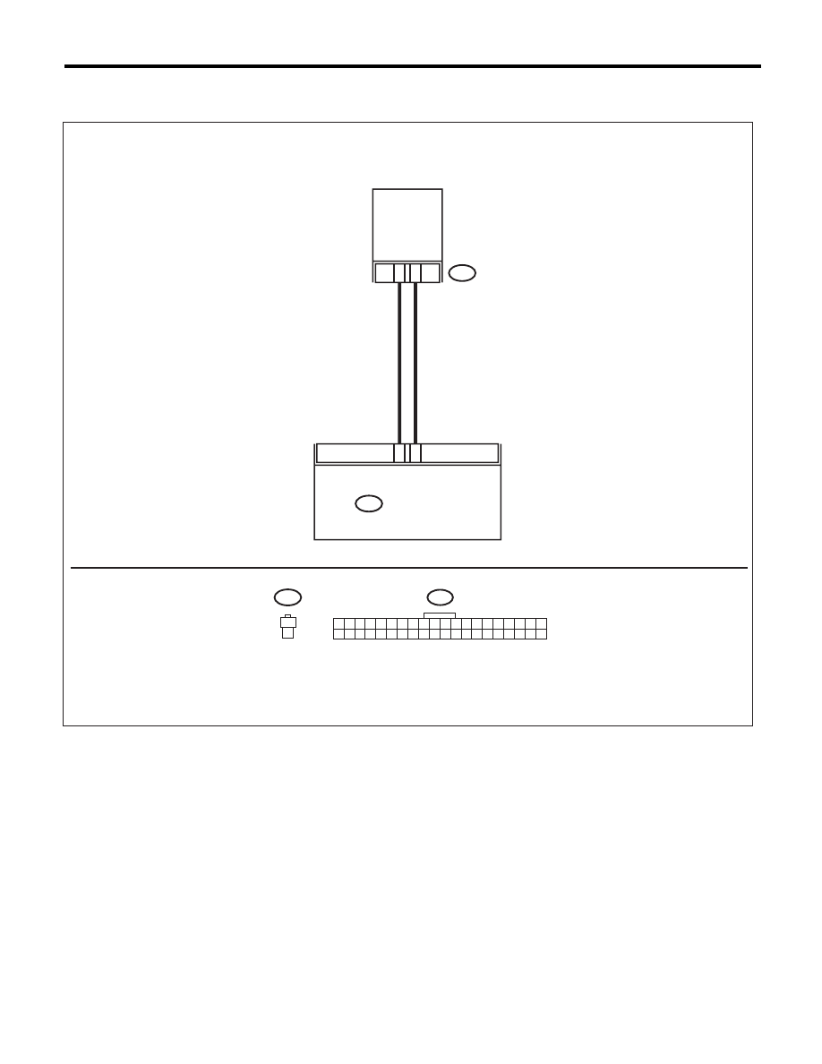
C: EVAPORATOR SENSOR
WIRING DIAGRAM:
25
27
B88
1
2
B88
B282
1
2
1
2
B282
AC-01650
1 2 3 4 5 6 7 8 9 10
21 22 23 24 25 26 27 28 29 30
11 12 13 14 15 16 17 18 19 20
31 32 33 34 35 36 37 38 39 40
AUTO A/C
CONTROL MODULE
EVAPORATOR
SENSOR

AC(diag)-34
Diagnostic Procedure for Sensors
HVAC SYSTEM (AUTO A/C) (DIAGNOSTICS)
Step
Check
Yes
No
1
CHECK EVAPORATOR SENSOR.
1) Turn the ignition switch to OFF.
2) Remove the glove box.
3) Disconnect the connector from evaporator
sensor.
4) Measure the resistance between connector
terminals of the evaporator sensor.
Terminals
No. 1 — No. 2:
Is the resistance approximately
3.3 k
: at 20°C (68°F) ?
Go to step 2.
Replace the evap-
orator sensor.
2
CHECK INPUT SIGNAL FOR EVAPORATOR
SENSOR.
1) Turn the ignition switch to ON.
2) Measure the voltage between connector
(B88) terminal and chassis ground.
Connector & terminal
(B88) No. 1 (+) — No. 2 (–):
Is the voltage approx. 5 V?
Go to step 6.
Go to step 3.
3
CHECK AUTO A/C CONTROL MODULE
OUTPUT SIGNAL.
1) Turn the ignition switch to OFF.
2) Remove the auto A/C control module.
3) Turn the ignition switch to ON.
4) Measure the voltage between connector
terminals of auto A/C control module.
Connector & terminal
(B282) No. 25 (+) — No. 27 (–):
Is the voltage approx. 5 V?
Go to step 4.
Go to step 6.
4
CHECK HARNESS CONNECTOR BETWEEN
AUTO A/C CONTROL MODULE AND EVAP-
ORATOR SENSOR.
1) Turn the ignition switch to OFF.
2) Disconnect the connector from the auto A/C
control module.
3) Measure the resistance of harness between
auto A/C control module and evaporator sensor.
Connector & terminal
(B88) No. 2 — (B282) No. 27:
Is the resistance less than 1
:? Go to step 5.
Repair the open
circuit of harness
between auto A/C
control module and
evaporator sensor.
5
CHECK HARNESS CONNECTOR BETWEEN
AUTO A/C CONTROL MODULE AND EVAP-
ORATOR SENSOR.
Measure the resistance of harness between
auto A/C control module and evaporator sensor.
Connector & terminal
(B88) No. 1 — (B282) No. 25:
Is the resistance less than 1
:? Go to step 6.
Repair the open
circuit of harness
between auto A/C
control module and
evaporator sensor.
6
CHECK POOR CONTACT.
Check poor contact of auto A/C control module
connector.
Is there poor contact in connec-
tor?
Repair the connec-
tor.
Replace the auto
A/C control mod-
ule.
AC(diag)-35
Diagnostic Procedure for Sensors
HVAC SYSTEM (AUTO A/C) (DIAGNOSTICS)
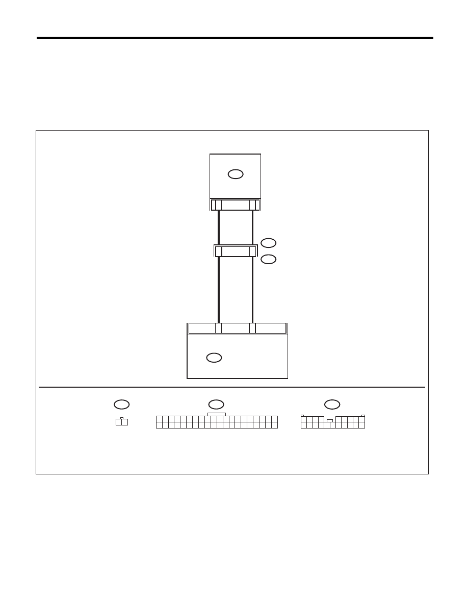
D: SUNLOAD SENSOR
TROUBLE SYMPTOM:
• Sensor identifies that sunlight is at maximum. Then, A/C system is controlled to COOL side.
• Sensor identifies that sunlight is at minimum. Then, A/C system is controlled to HOT side.
NOTE:
When the sunload sensor check is performed indoors or in the shade, it could be diagnosed as having an
open circuit. Always check the sunload sensor with the sun shining on it.
WIRING DIAGRAM:
B282
i51
B282
8
6
2
1
i3
B38
i51
1 2
3
2
1 2 3 4
5 6 7 8 9
10 11 12 13 14 15 16 17 18 19 20
B38
AC-01651
1 2 3 4 5 6 7 8 9 10
21 22 23 24 25 26 27 28 29 30
11 12 13 14 15 16 17 18 19 20
31 32 33 34 35 36 37 38 39 40
SUNLOAD SENSOR
AUTO A/C
CONTROL MODULE
Нет комментариевНе стесняйтесь поделиться с нами вашим ценным мнением.
Текст