Subaru Legacy IV (2008 year). Service manual — part 736
5AT-68
Extension Case
AUTOMATIC TRANSMISSION
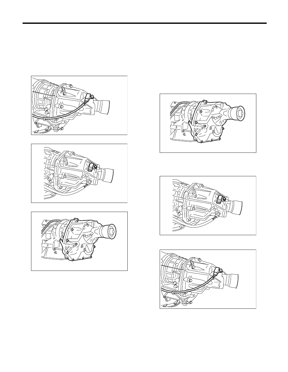
25.Extension Case
A: REMOVAL
1) Remove the transmission assembly. <Ref. to
5AT-39, REMOVAL, Automatic Transmission As-
sembly.>
2) Disconnect the rear vehicle speed sensor con-
nector.
3) Remove the rear vehicle speed sensor.
4) Remove the extension case.
B: INSTALLATION
1) Attach the selected reduction driven gear shim
to end surface of reduction driven gear with vase-
line. <Ref. to 5AT-76, ADJUSTMENT, Reduction
Driven Gear.>
2) Install the extension case.
NOTE:
Use a new gasket.
Tightening torque:
25 N·m (2.5 kgf-m, 18.4 ft-lb)
3) Install the rear vehicle speed sensor.
Tightening torque:
7 N·m (0.7 kgf-m, 5.2 ft-lb)
4) Connect the rear vehicle speed sensor connec-
tor.
5) Install the transmission assembly. <Ref. to 5AT-
43, INSTALLATION, Automatic Transmission As-
sembly.>
AT-04218
AT-04261
AT-03226
AT-03226
AT-04261
AT-04218
5AT-69
Extension Case
AUTOMATIC TRANSMISSION
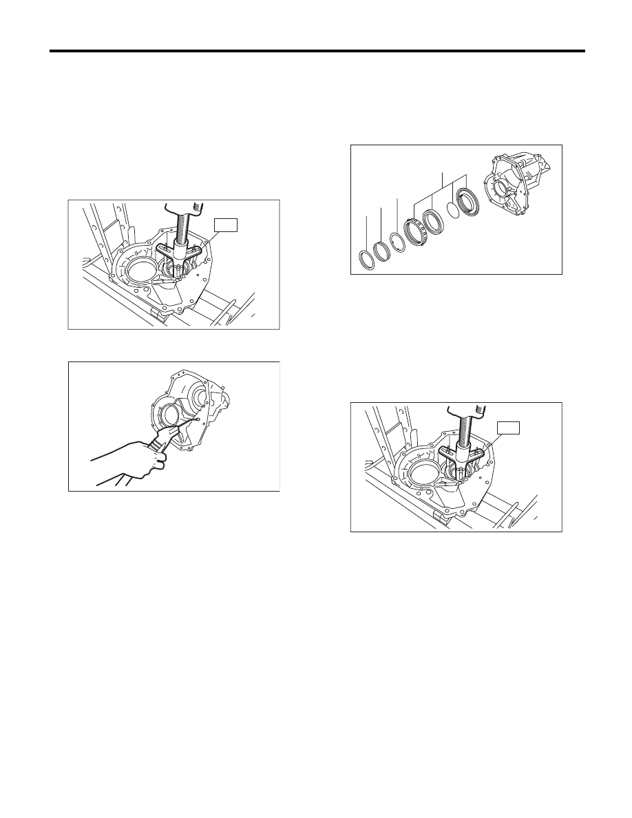
C: DISASSEMBLY
1) Take out the transfer clutch and multi-plate
clutch hub assembly by lightly tapping the end of
rear drive shaft.
NOTE:
Be careful not to damage the oil seal of the exten-
sion.
2) Remove the snap ring using the ST and press.
ST
18762AA000
COMPRESSOR SPECIAL
TOOL
3) Remove the clutch piston by applying com-
pressed air.
4) Remove the dust cover from extension case.
5) Remove the oil seal from the extension case.
D: ASSEMBLY
1) Press-fit the new oil seal using ST and the press.
ST
498057300
INSTALLER
2) Press-fit the dust cover.
3) Insert the transfer clutch assembly, spring re-
tainer, return spring and clutch spring retainer.
4) Using the ST and compressor, install the snap
ring.
ST
18762AA000
COMPRESSOR SPECIAL
TOOL
5) Install the transfer clutch. <Ref. to 5AT-70, IN-
STALLATION, Transfer Clutch.>
6) Install the multi-plate hub assembly.
E: INSPECTION
• Use compressed air to make sure the extension
case routes are not clogged or leaking.
• Inspect the extension end play, and adjust it to
within the standard value. <Ref. to 5AT-70, AD-
JUSTMENT, Transfer Clutch.>
AT-03228
ST
AT-03229
(A) Clutch spring retainer
(B) Return spring
(C) Spring retainer
(D) Transfer clutch piston ASSY
AT-03230
(A)
(B)
(C)
(D)
AT-03228
ST
5AT-70
Transfer Clutch
AUTOMATIC TRANSMISSION
26.Transfer Clutch
A: REMOVAL
1) Remove the transmission assembly from vehicle
body. <Ref. to 5AT-39, REMOVAL, Automatic
Transmission Assembly.>
2) Remove the extension case, and then remove
the transfer clutch. <Ref. to 5AT-68, REMOVAL,
Extension Case.> <Ref. to 5AT-69, DISASSEM-
BLY, Extension Case.>
B: INSTALLATION
1) Select the rear drive shaft shim. <Ref. to 5AT-70,
ADJUSTMENT, Transfer Clutch.>
2) Select driven plate No. 3 <Ref. to 5AT-70, AD-
JUSTMENT, Transfer Clutch.>
3) Install the extension case. <Ref. to 5AT-68, IN-
STALLATION, Extension Case.>
4) Install the transmission assembly to the vehicle.
<Ref. to 5AT-43, INSTALLATION, Automatic
Transmission Assembly.>
C: INSPECTION
• Inspect the drive plate facing for wear and dam-
age.
• Make sure the snap ring is not worn and the re-
turn spring has no permanent distortion, damage,
or deformation.
• Check that the D-ring is not damaged.
• Inspect the extension end play, and adjust it to
within the standard value. <Ref. to 5AT-70, AD-
JUSTMENT, Transfer Clutch.>
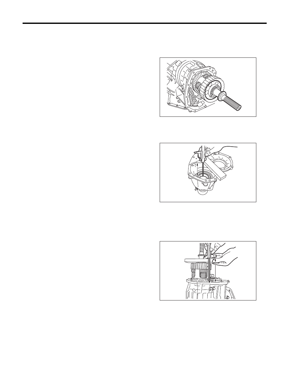
D: ADJUSTMENT
1. REAR DRIVE SHAFT SHIM SELECTION
1) Insert the rear drive shaft into the reduction drive
gear and center differential assembly.
2) Using the ST, measure the depth “A”, which is
from mating surface of extension case to ball bear-
ing outer ring contact surface.
ST
398643600
GAUGE
3) Using the ST, measure the height “B” from the
AT main case mating surface to ball bearing outer
ring contact surface.
ST
398643600
GAUGE
A Measured value
B Measured value
AT-03231
AT-03232
A
AT-03233
B
5AT-71
Transfer Clutch
AUTOMATIC TRANSMISSION
4) Calculation formula:
When clearances are 0.05 mm (0.0020 in):
T (mm) = A – B + 0.23
[T (in) = A – B + 0.0091]
When clearances are 0.25 mm (0.0098 in):
T (mm) = A – B + 0.03
[T (in) = A – B + 0.0012]
A: Depth from end of extension case to ball bearing
outer ring contact surface
B: Height from end of AT main case contact surface
to the ball bearing outer ring contact surface
T: Shim thickness
Standard:
0.05 — 0.25 mm (0.0020 — 0.0098 in)
NOTE:
Calculation formula for “T” above is applied when
measuring with the ST (398643600 GAUGE).
When not using the ST,
When clearances are 0.05 mm (0.0020 in):
T (mm) = (A –
D) – ((B – E) – 0.28) – 0.05
[T (in) = (A –
D) – ((B – E) – 0.0110) – 0.0020]
When clearances are 0.25 mm (0.0098 in):
T (mm) = (A –
D) – ((B – E) – 0.28) – 0.25
[T (in) = (A –
D) – ((B – E) – 0.0110) – 0.0098]
is applied.
T: Shim thickness
A: Depth from end of extension case to ball bearing
outer ring contact surface
B: Height from end of AT main case contact surface
to the ball bearing outer ring contact surface
D: Thickness of collar used when measuring “A”
E: Thickness of collar used when measuring “B”
0.28 (0.0110): Gasket thickness (Unit mm (in))
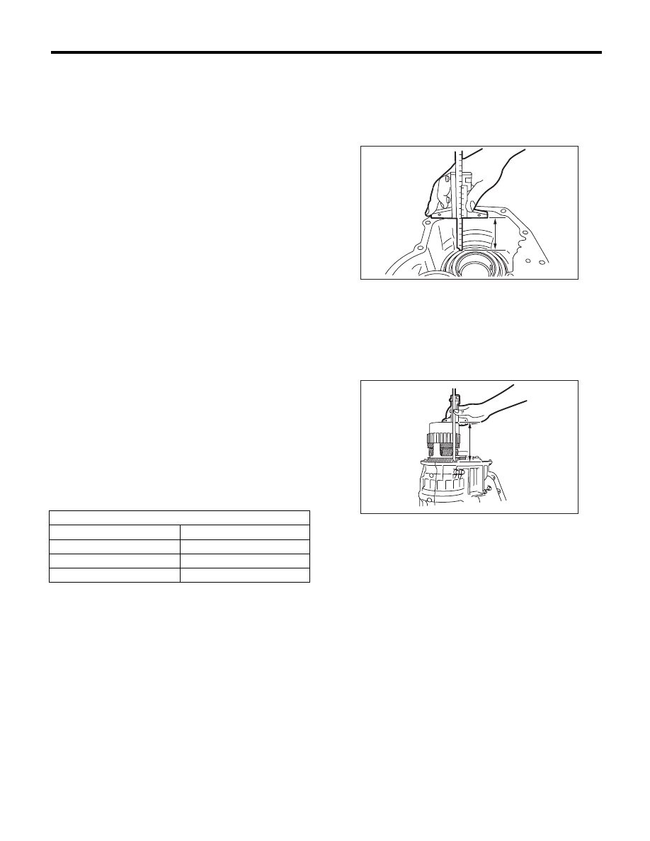
2. SELECTION OF DRIVEN PLATE NO. 3
1) Install the drive plate and driven plate to the cen-
ter differential carrier.
2) Measure the depth “A” from the mating surface
of the extension case to the multi-plate clutch
(LSD) piston.
3) Using the ST, measure the height “B” from the
AT main case mating surface to end of ST, and
then subtract the thickness of ST (piston guide) (50
mm (1.97 in)) from measured value.
ST
398744300
PISTON GUIDE
Adjustment shim
Part No.
Thickness mm (in)
33281AA040
0.2 (0.008)
33281AA050
0.5 (0.020)
33281AA060
0.3 (0.012)
A Measured value
B Measured value
AT-03234
A
AT-03235
B
Нет комментариевНе стесняйтесь поделиться с нами вашим ценным мнением.
Текст