Subaru Legacy IV (2008 year). Service manual — part 683
4AT-80
Converter Case
AUTOMATIC TRANSMISSION
30.Converter Case
A: REMOVAL
1) Remove the transmission assembly from vehicle
body. <Ref. to 4AT-35, REMOVAL, Automatic
Transmission Assembly.>
2) Pull out the torque converter clutch assembly.
<Ref. to 4AT-67, REMOVAL, Torque Converter
Clutch Assembly.>
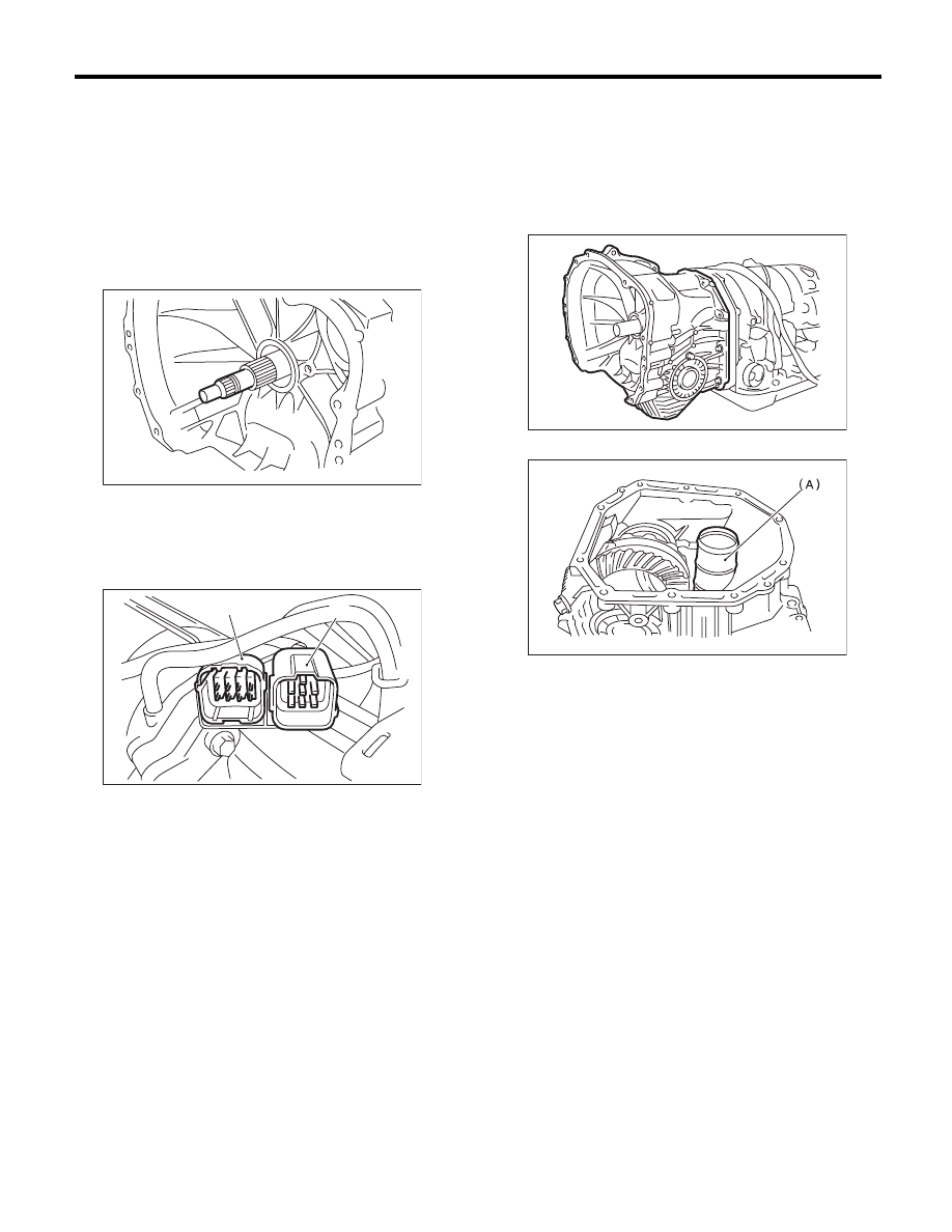
3) Remove the input shaft.
4) Lift up the lever on the rear side of transmission
harness connector, and then disconnect it from the
stay.
5) Disconnect the inhibitor switch connector from
the stay.
6) Remove the air breather hose. <Ref. to 4AT-65,
REMOVAL, Air Breather Hose.>
7) Remove the oil charge pipe. <Ref. to 4AT-66,
REMOVAL, Oil Charge Pipe.>
8) Remove the ATF inlet and outlet pipes. <Ref. to
4AT-62, REMOVAL, ATF Cooler Pipe and Hose.>
9) Remove the converter case alignment bolt, and
then separate the transmission case and converter
case by lightly tapping with a plastic hammer.
NOTE:
• Be careful not to damage the oil seal and bush-
ing in the converter case with the oil pump cover.
• Do not loosen the rubber seal.
10) Remove the seal pipe.
11) Remove the front differential assembly. <Ref.
to 4AT-95, REMOVAL, Front Differential Assem-
bly.>
12) Remove the oil seal from converter case.
(A) Transmission harness connectors
(B) Inhibitor switch connector
AT-00114
AT-01351
(B)
(A)
(A) Seal pipe
AT-04678
AT-00176
4AT-81
Converter Case
AUTOMATIC TRANSMISSION
B: INSTALLATION
1) Check the appearance of each component and
clean them.
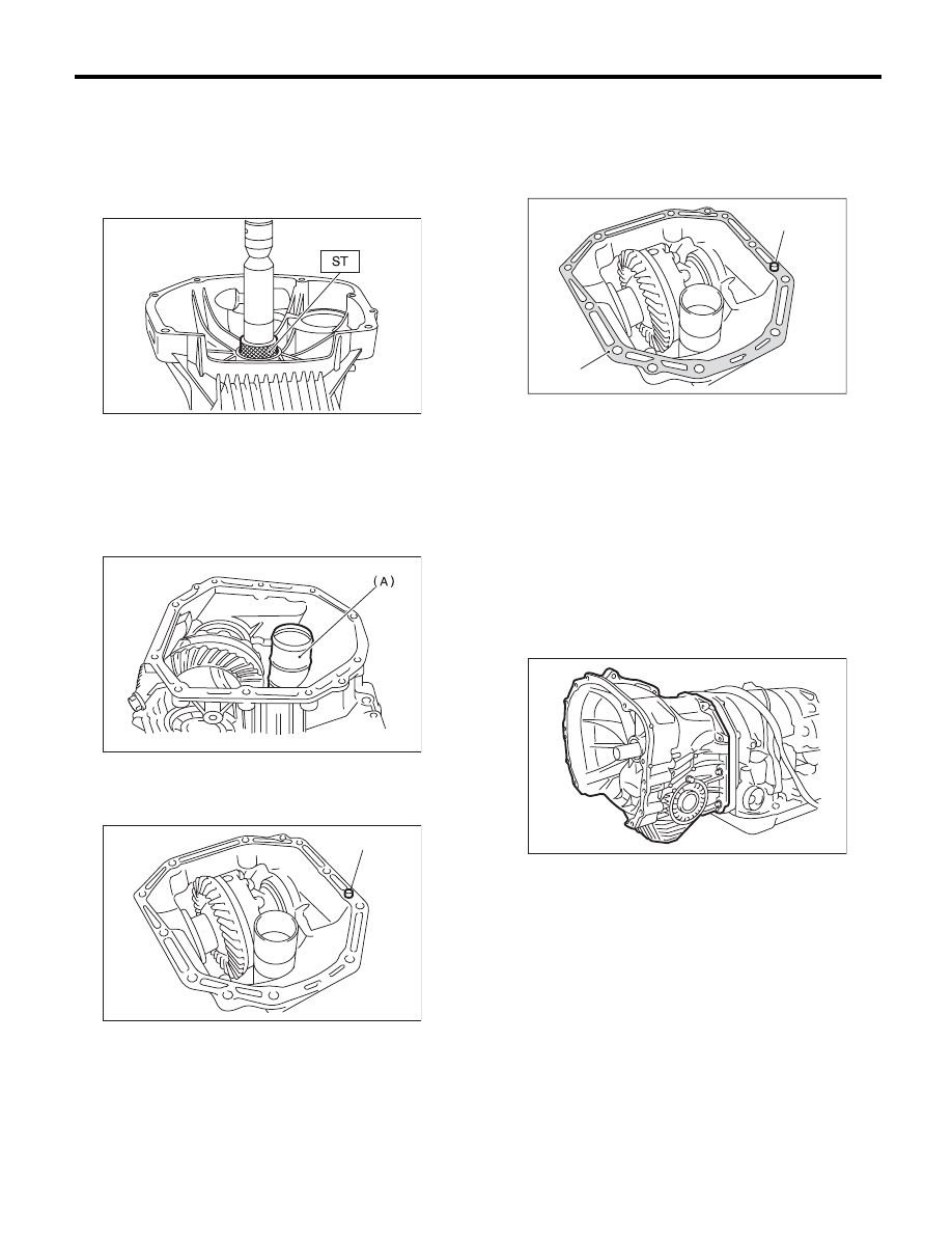
2) Press-fit the new oil seal to the converter case
using the ST.
ST
398437700
DRIFT
3) Install the front differential assembly to the case.
<Ref. to 4AT-95, INSTALLATION, Front Differen-
tial Assembly.>
4) Install the right and left side retainers. <Ref. to
4AT-99, ADJUSTMENT, Front Differential Assem-
bly.>
5) Install new seal pipe to converter case.
6) Install new rubber seal to the converter case.
7) Apply proper amount of liquid gasket to the en-
tire matching surface of converter case.
Liquid gasket:
THREE BOND 1215 (Part No. 004403007) or
equivalent
8) Install the converter case without damaging
bushing and oil seal.
NOTE:
Use new bolts for the oil charge pipe.
Tightening torque:
Oil charge pipe section
38 N·m (3.9 kgf-m, 28.0 ft-lb)
Excluding the oil charge pipe section
41 N·m (4.2 kgf-m, 30.2 ft-lb)
9) Insert the inhibitor switch connector and trans-
mission harness connector onto the stay.
10) Install the air breather hose. <Ref. to 4AT-65,
INSTALLATION, Air Breather Hose.>
11) Install the ATF cooler pipe. <Ref. to 4AT-63, IN-
STALLATION, ATF Cooler Pipe and Hose.>
12) Install the oil charge pipe with O-ring. <Ref. to
4AT-66, INSTALLATION, Oil Charge Pipe.>
(A) Seal pipe
(A) Rubber seal
AT-00177
AT-00176
AT-00178
(A)
(A) THREE BOND 1215
(B) Rubber seal
(B)
(A)
AT-00179
AT-04678
4AT-82
Converter Case
AUTOMATIC TRANSMISSION
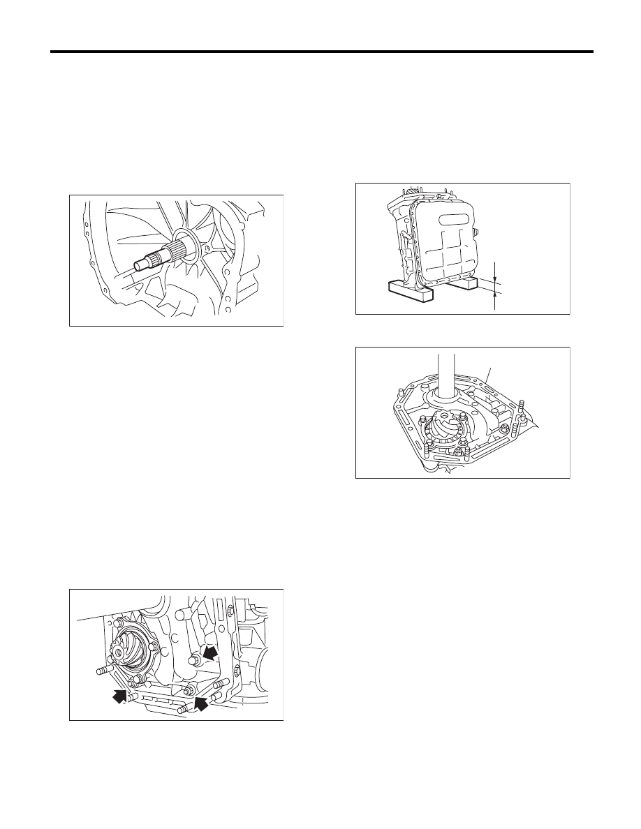
13) Insert the input shaft while rotating it lightly by
hand, and then check the amount of protrusion.
Normal protrusion A:
50 — 55 mm (1.97 — 2.17 in)
14) Install the torque converter clutch assembly.
<Ref. to 4AT-67, INSTALLATION, Torque Convert-
er Clutch Assembly.>
15) Install the transmission assembly to the vehi-
cle. <Ref. to 4AT-38, INSTALLATION, Automatic
Transmission Assembly.>
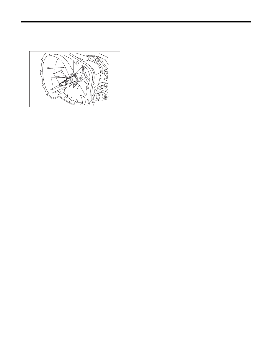
C: INSPECTION
Measure the backlash, and then adjust it to be with-
in standard values. <Ref. to 4AT-92, ADJUST-
MENT, Drive Pinion Shaft Assembly.>
A Measured value
AT-03204
A
4AT-83
Oil Pump Housing
AUTOMATIC TRANSMISSION
31.Oil Pump Housing
A: REMOVAL
1) Remove the transmission assembly from vehicle
body. <Ref. to 4AT-35, REMOVAL, Automatic
Transmission Assembly.>
2) Pull out the torque converter clutch assembly.
<Ref. to 4AT-67, REMOVAL, Torque Converter
Clutch Assembly.>
3) Remove the input shaft.
4) Lift up the lever on the rear side of transmission
harness connector, and then remove it from the
stay.
5) Remove the inhibitor switch connector from the
stay.
6) Remove the oil charge pipe. <Ref. to 4AT-66,
REMOVAL, Oil Charge Pipe.>
7) Remove the ATF inlet and outlet pipes. <Ref. to
4AT-62, REMOVAL, ATF Cooler Pipe and Hose.>
8) Separate the converter case and transmission
case. <Ref. to 4AT-80, REMOVAL, Converter
Case.>
9) Separate the transmission case and extension
case section. <Ref. to 4AT-68, REMOVAL, Exten-
sion Case.>
10) Remove the reduction drive gear. <Ref. to 4AT-
77, REMOVAL, Reduction Drive Gear.>
11) Remove the reduction driven gear. <Ref. to
4AT-75, REMOVAL, Reduction Driven Gear.>
12) Loosen the oil pump housing mounting bolts.
13) Place two wooden blocks on the workbench,
and stand the transmission case with the rear end
facing down.
NOTE:
• Be careful not to scratch the rear mating surface
of the transmission case.
• Check the height of the wooden blocks to avoid
damaging the parking rod protruding from the mat-
ing surface, and the drive pinion.
14) Remove the oil pump housing and adjusting
thrust washer.
AT-00114
AT-01034
(A) Oil pump housing
AT-04862
(2.17in)
55mm
AT-00182
(A)
Нет комментариевНе стесняйтесь поделиться с нами вашим ценным мнением.
Текст