Subaru Legacy IV (2008 year). Service manual — part 681
4AT-72
Transfer Clutch
AUTOMATIC TRANSMISSION
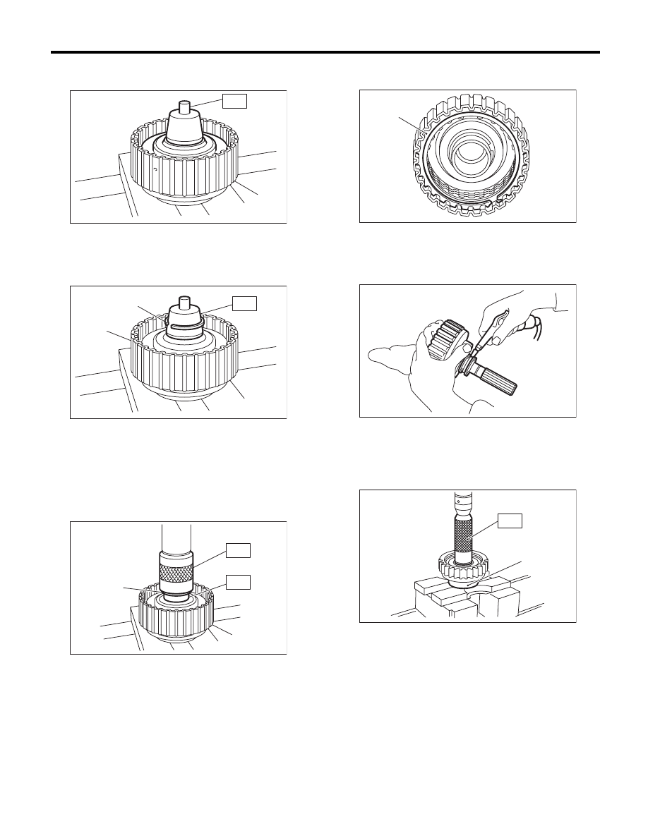
4) Attach the ST to the rear drive shaft.
ST
499257300
SNAP RING OUTER GUIDE
5) Install the snap ring to the ST.
ST
499257300
SNAP RING OUTER GUIDE
6) Install the snap ring to the rear drive shaft using
ST1 and ST2.
ST1
499257300
SNAP RING OUTER GUIDE
ST2
499247400
INSTALLER
7) Install the driven plate, drive plate, retaining
plate and snap ring.
8) Apply compressed air to see if the assembled
parts move smoothly.
9) Check clearance between the snap ring and
pressure plate. <Ref. to 4AT-73, INSPECTION,
Transfer Clutch.>
10) Press-fit new ball bearing using ST.
ST
899580100
INSTALLER
(A) Rear drive shaft
(A) Snap ring
(B) Rear drive shaft
(A) Snap ring
(B) Rear drive shaft
AT-00135
(A)
ST
AT-00136
(A)
(B)
ST
AT-00137
(A)
(B)
ST2
ST1
(A) Snap ring
(A) Ball bearing
AT-00138
(A)
AT-00139
AT-00140
(A)
ST
4AT-73
Transfer Clutch
AUTOMATIC TRANSMISSION
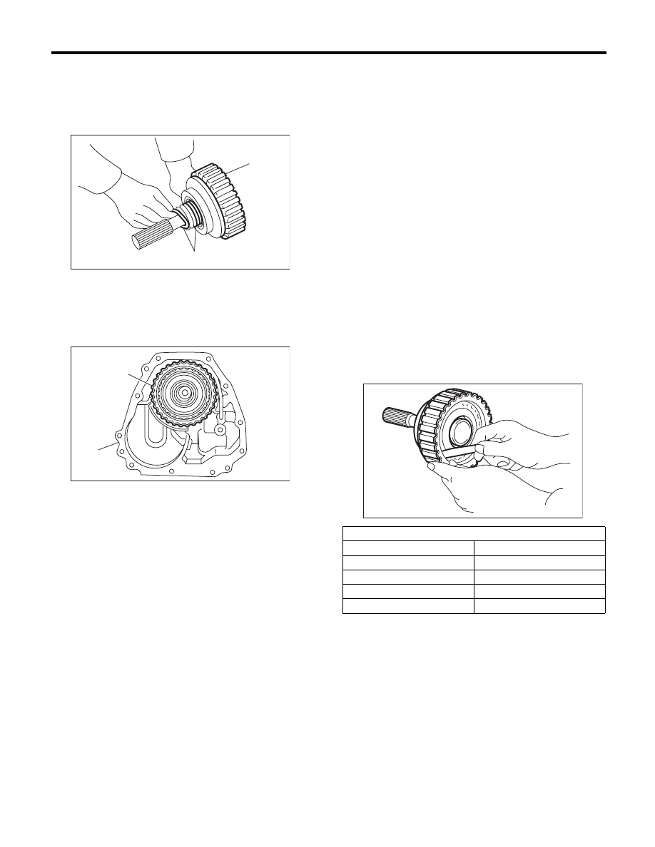
11) Apply vaseline to a new seal ring and attach to
the seal ring groove of the rear drive shaft.
NOTE:
While installing the seal ring, not to stretch the seal
ring excessively.
12) Install the transfer clutch assembly while taking
care not to damage the seal ring.
E: INSPECTION
• Inspect the drive plate facing for wear and dam-
age.
• Make sure the snap ring is not worn and the re-
turn spring has no permanent distortion, damage,
or deformation.
• Inspect the D-ring for damage.
• Inspect the extension end play, and adjust it to
within the standard value. <Ref. to 4AT-74, AD-
JUSTMENT, Transfer Clutch.>
1) Check the clearance between the snap ring and
retaining plate.
2) Before measuring clearance, place same thick-
ness shims on both sides to prevent the retaining
plate from tilting.
3) If the clearance exceeds the service limits, re-
place the plate set (drive plate and driven plate),
and select and adjust a retaining plate to be within
the initial standard value.
Initial standard:
0.7 — 1.1 mm (0.028 — 0.043 in)
Limit thickness:
1.6 mm (0.063 in)
4) Check for tight corner braking phenomenon
when the vehicle is moved forward with the steer-
ing fully turned. If tight corner braking occurs, per-
form the following procedures.
(1) With the steering wheel held at fully turned
position, drive the vehicle in “D” range and with
vehicle speed at approx. 5 km/h (3 MPH) in
both clockwise and counterclockwise directions
for approx. ten times each, while repeating ac-
celeration and braking intermittently.
(2) If the tight corner braking phenomenon still
persists, drive the vehicle again in a circle for
several laps.
(A) Seal ring
(B) Rear drive shaft
(A) Transfer clutch ASSY
(B) Extension case
AT-00141
(A)
(B)
AT-00125
(A)
(B)
Retaining plate
Part No.
Thickness mm (in)
31593AA151
3.3 (0.130)
31593AA161
3.7 (0.146)
31593AA171
4.1 (0.161)
31593AA181
4.5 (0.177)
AT-00142
4AT-74
Transfer Clutch
AUTOMATIC TRANSMISSION
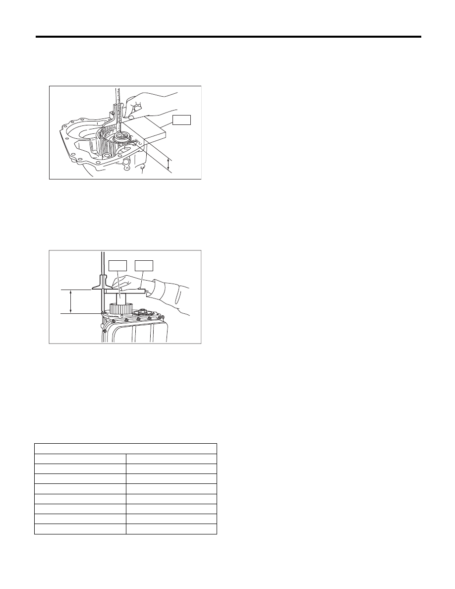
F: ADJUSTMENT
1) Measure the distance “A” from the end of ST to
the rear drive shaft using the ST.
ST
398643600
GAUGE
2) Measure distance “B” from the transmission
case mating surface to the end of ST using ST1
and ST2.
ST1
398643600
GAUGE
ST2
499577000
GAUGE
3) Calculation formula:
T = A – B + 35.4 mm
[T = A – B + 1.3937 in]
T: Thrust needle bearing thickness
A: Distance from the end of the ST to end of rear
drive shaft
B: Distance from the mating surface of the trans-
mission case to the end of the ST
A Measured value
B Measured value
Thrust needle bearing
Part No.
Thickness mm (in)
806536020
3.8 (0.150)
806535030
4.0 (0.157)
806535040
4.2 (0.165)
806535050
4.4 (0.173)
806535060
4.6 (0.181)
806535070
4.8 (0.189)
806535090
5.0 (0.197)
A
ST
AT-01029
ST2
ST1
B
AT-02210
4AT-75
Reduction Driven Gear
AUTOMATIC TRANSMISSION
27.Reduction Driven Gear
A: REMOVAL
1) Remove the transmission assembly from vehicle
body. <Ref. to 4AT-35, REMOVAL, Automatic
Transmission Assembly.>
2) Remove the rear vehicle speed sensor, and sep-
arate the extension case from transmission case.
<Ref. to 4AT-68, REMOVAL, Extension Case.>
3) Set the range select lever to the “P” range.
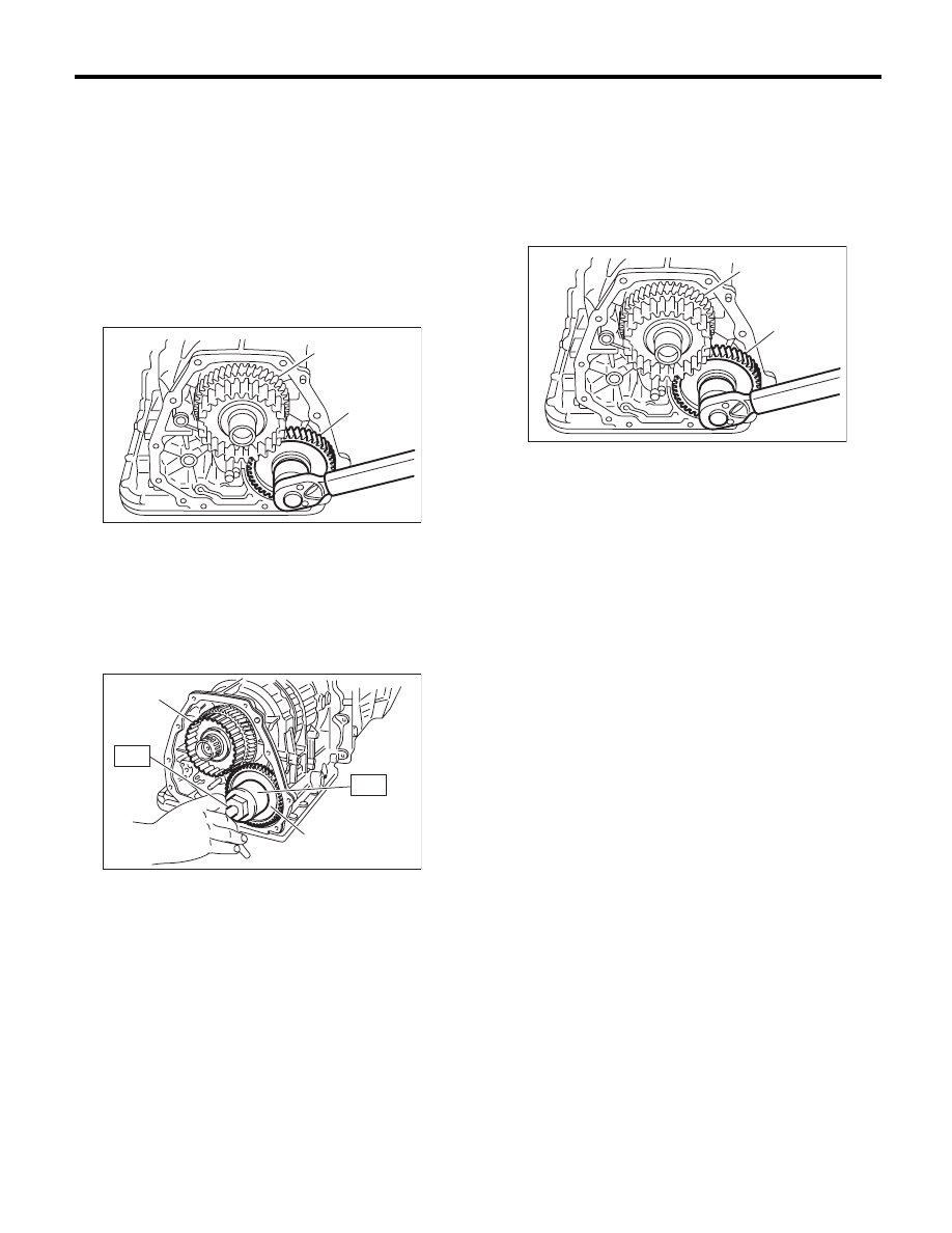
4) Lift the crimped section, and then remove the
lock nut.
5) Using the ST1 and ST2, extract the reduction
driven gear.
ST1
499737000
PULLER
ST2
899524100
PULLER SET
B: INSTALLATION
1) Set the range select lever to the “P” range.
2) Using a plastic hammer, install the reduction
driven gear assembly and the new washer, and
tighten the new drive pinion lock nut.
Tightening torque:
100 N·m (10.2 kgf-m, 73.8 ft-lb)
3) After tightening, stake the lock nut securely.
4) Join the transmission case and the extension
case, and then install the rear vehicle speed sen-
sor. <Ref. to 4AT-68, INSTALLATION, Extension
Case.>
5) Install the transmission assembly to the vehicle.
<Ref. to 4AT-38, INSTALLATION, Automatic
Transmission Assembly.>
(A) Reduction driven gear
(B) Reduction drive gear
(A) Reduction driven gear
(B) Reduction drive gear
AT-02212
(A)
(B)
AT-04870
(A)
(B)
ST1
ST2
(A) Reduction driven gear
(B) Reduction drive gear
AT-02212
(A)
(B)
Нет комментариевНе стесняйтесь поделиться с нами вашим ценным мнением.
Текст