Subaru Legacy IV (2008 year). Service manual — part 684
4AT-84
Oil Pump Housing
AUTOMATIC TRANSMISSION
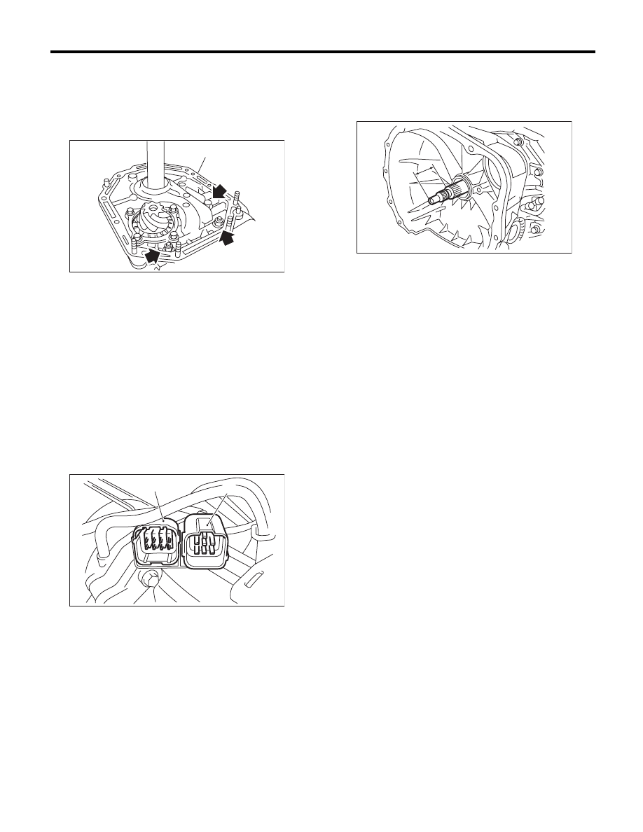
B: INSTALLATION
1) Secure the oil pump housing with two nuts and a
bolt.
Tightening torque:
42 N·m (4.3 kgf-m, 31.0 ft-lb)
2) Install the converter case to the transmission
case assembly. <Ref. to 4AT-81, INSTALLATION,
Converter Case.>
3) Install the reduction driven gear. <Ref. to 4AT-
75, INSTALLATION, Reduction Driven Gear.>
4) Install the reduction drive gear. <Ref. to 4AT-77,
INSTALLATION, Reduction Drive Gear.>
5) Join the transmission case and the extension
case, and then install the rear vehicle speed sen-
sor. <Ref. to 4AT-68, INSTALLATION, Extension
Case.>
6) Insert the inhibitor switch connector and trans-
mission harness connector onto the stay.
7) Install the ATF cooler pipe. <Ref. to 4AT-63, IN-
STALLATION, ATF Cooler Pipe and Hose.>
8) Install the oil charge pipe together with an O-
ring. <Ref. to 4AT-66, INSTALLATION, Oil Charge
Pipe.>
9) Insert the input shaft while rotating it lightly by
hand, and then check the amount of protrusion.
Normal protrusion A:
50 — 55 mm (1.97 — 2.17 in)
10) Install the torque converter clutch assembly.
<Ref. to 4AT-67, INSTALLATION, Torque Convert-
er Clutch Assembly.>
11) Install the transmission assembly to the vehi-
cle. <Ref. to 4AT-38, INSTALLATION, Automatic
Transmission Assembly.>
(A) Oil pump housing
(A) Transmission harness connectors
(B) Inhibitor switch connector
AT-01035
(A)
AT-01351
(B)
(A)
A Measured value
AT-03204
A
4AT-85
Oil Pump Housing
AUTOMATIC TRANSMISSION
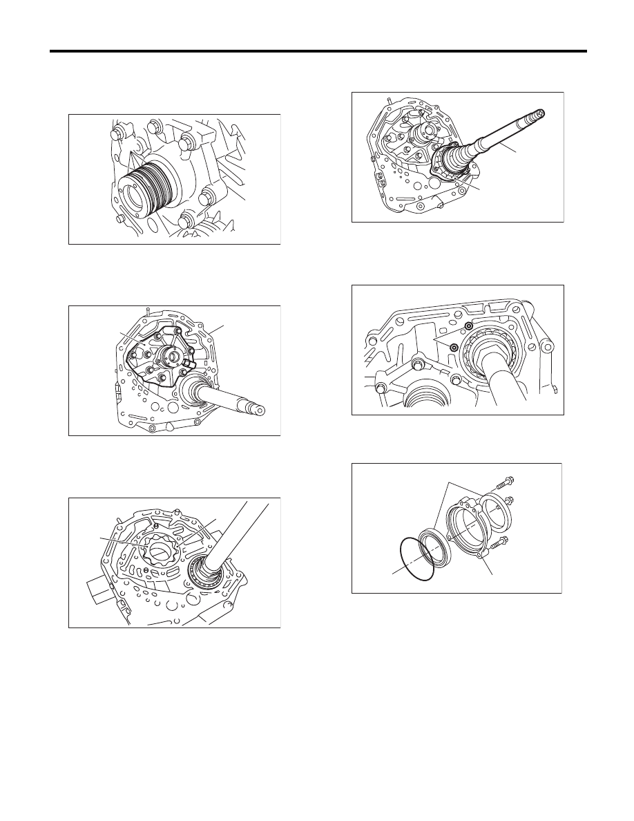
C: DISASSEMBLY
1. OIL PUMP COVER
1) Remove the four seal rings.
2) Remove attachment bolts, then remove the cov-
er by lightly tapping the end of the stator shaft.
3) Remove the oil pump inner and outer rotors.
2. OIL SEAL RETAINER
1) Remove the oil seal retainer.
2) Remove the O-ring.
3) Remove the oil seal from the oil seal retainer.
(A) Seal ring
(A) Oil pump cover
(B) Oil pump housing
(A) Inner rotor
(B) Outer rotor
AT-00189
(A)
AT-00190
(A)
(B)
AT-01036
(A)
(B)
(A) Oil seal retainer
(B) Drive pinion shaft
(A) O-ring
(A) Oil seal
(B) Oil seal retainer
AT-00183
(A)
(B)
AT-03361
(A)
AT-03360
(A)
(B)
4AT-86
Oil Pump Housing
AUTOMATIC TRANSMISSION
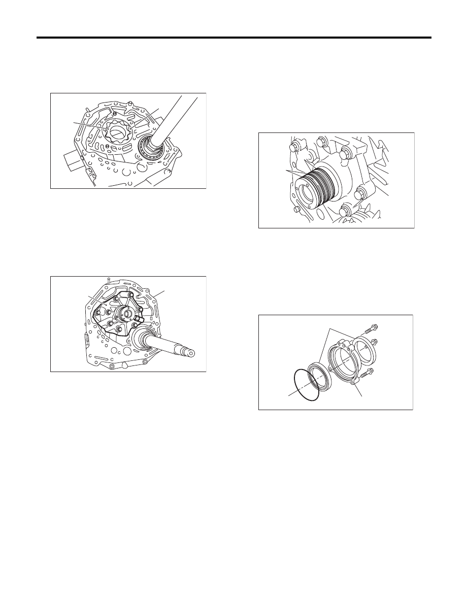
D: ASSEMBLY
1. OIL PUMP COVER
1) Install the oil pump rotor assembly to oil pump
housing.
2) Align both pivots with the pivot holes of the cov-
er, and then install the oil pump cover while being
careful not to apply excessive force to the pivots.
Tightening torque:
25 N·m (2.5 kgf-m, 18.4 ft-lb)
3) After assembling, turn the oil pump shaft to
check for smooth rotation of rotor.
4) Apply vaseline to the oil seal retainer and new
seal rings, and install them. After installing, adjust
the tooth contact with the drive pinion backlash.
<Ref. to 4AT-88, ADJUSTMENT, Oil Pump Hous-
ing.>
NOTE:
There are two types of seals. They are identified by
color. Install at the proper positions by referring to
the figure.
2. OIL SEAL RETAINER
1) Apply ATF to two new oil seals and install them
to the oil seal retainer in the proper direction using
the ST.
ST
499247300
INSTALLER
(A) Inner rotor
(B) Outer rotor
(A) Oil pump cover
(B) Oil pump housing
AT-01036
(A)
(B)
AT-00190
(A)
(B)
(A) Seal ring (Black)
(B) Seal ring (Brown)
(A) Oil seal
(B) Oil seal retainer
AT-01307
(A)
(B)
AT-03360
(A)
(B)
4AT-87
Oil Pump Housing
AUTOMATIC TRANSMISSION
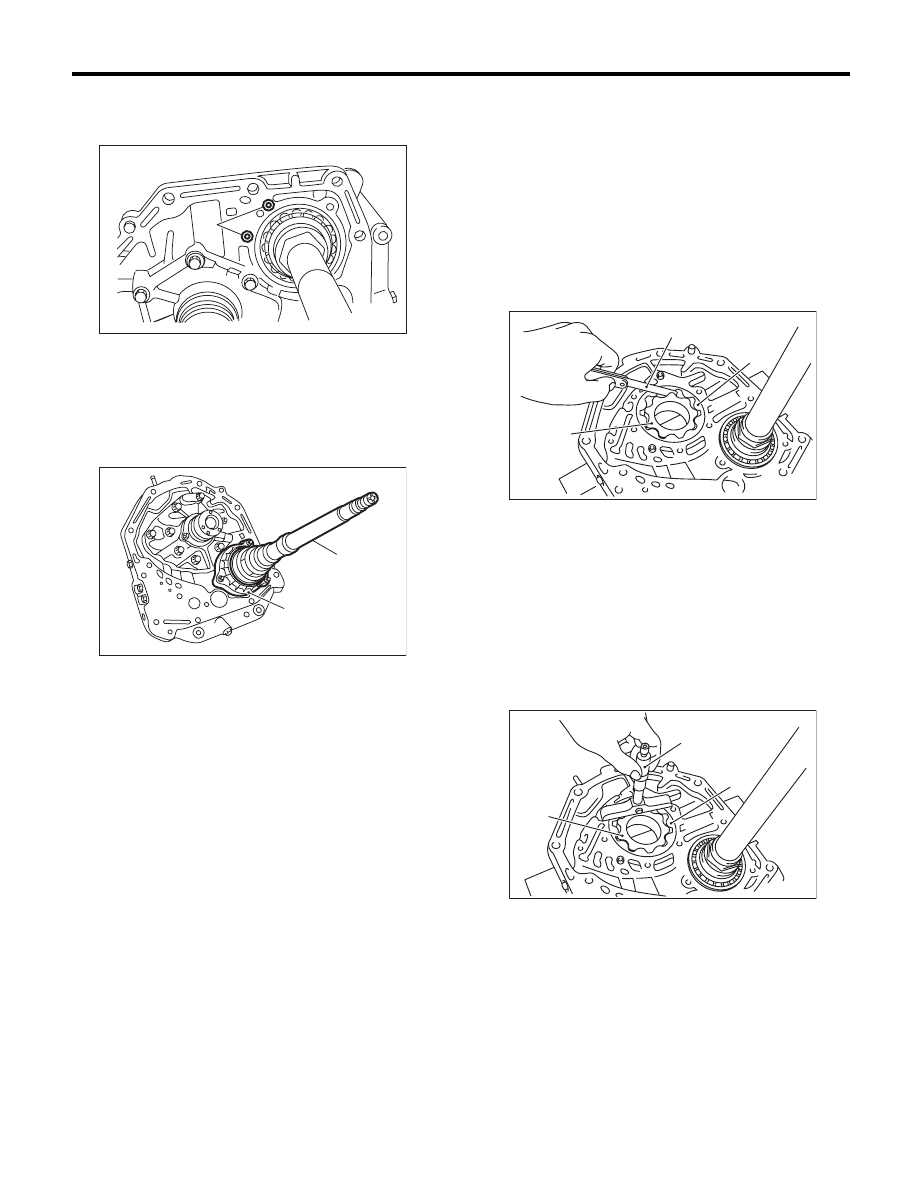
2) Apply ATF to a new O-ring and attach to the oil
seal retainer. Install the seal to the oil pump hous-
ing bore.
3) Install the oil seal being careful not to damage oil
seal lip, and secure it using three bolts.
Tightening torque:
7 N·m (0.7 kgf-m, 5.2 ft-lb)
E: INSPECTION
1) Check the seal ring and oil seal for breaks and
damage.
2) Check other parts for dents or faults.
3) Oil pump rotor assembly selection
(1) Tip clearance
Install the inner rotor and outer rotor to the oil
pump. With rotor gears facing each other, mea-
sure the crest-to-crest clearance.
Tip clearance:
0.02 — 0.15 mm (0.0008 — 0.0059 in)
(2) Side clearance
Set a depth gauge to oil pump housing, then
measure the oil pump housing-to-rotor clear-
ance.
Side clearance:
0.02 — 0.04 mm (0.0008 — 0.0016 in)
(A) O-ring
(A) Oil seal retainer
(B) Drive pinion shaft
AT-03361
(A)
AT-00183
(A)
(B)
(A) Thickness gauge
(B) Inner rotor
(C) Outer rotor
(A) Depth gauge
(B) Inner rotor
(C) Outer rotor
AT-01038
(B)
(C)
(A)
AT-01039
(A)
(B)
(C)
Нет комментариевНе стесняйтесь поделиться с нами вашим ценным мнением.
Текст