Subaru Legacy III (2000-2003 year). Service manual — part 1013
WI-6
WIRING SYSTEM
BASIC DIAGNOSTICS PROCEDURE
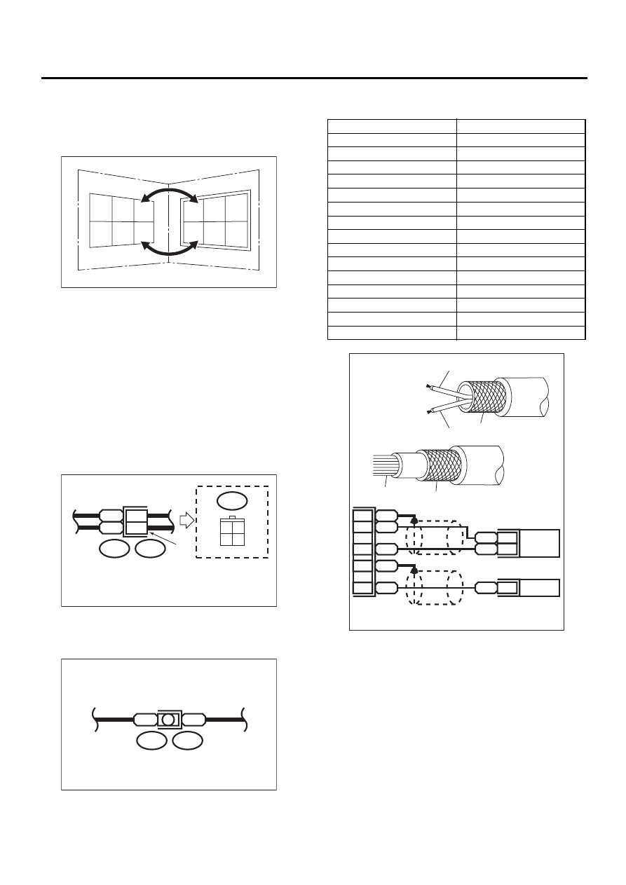
• When one set of connectors is viewed from the
front side, the pole numbers of one connector are
symmetrical to those of the other. When these two
connectors are connected as a unit, the poles
which have the same number are joined.
• Electrical wiring harness:
The connectors are numbered along with the num-
ber of poles, external colors, and mating connec-
tions in the accompanying list.
• The sketch of each connector in the wiring dia-
gram usually shows the (A) side of the connector.
The relationship between the wire color, terminal
number and connector is described in figure.
NOTE:
A wire which runs in one direction from a connector
terminal sometimes may have a different color from
that which runs in the other direction from that ter-
minal.
• In wiring diagram, connectors which have no ter-
minal number refer to one-pole types. Sketches of
these connectors are omitted intentionally.
• The following color codes are used to indicate
the colors of the wires used.
WI-00107
1
1
2
2
3
3
4
4
5
5
6
6
WI-00108
Wire color :
BR (No. 1 terminal)
RW (No. 3 terminal)
i2
3 4
1 2
BR
RW
i2
F4
1
3
(A)
WI-00109
B
B
B15
F10
Color code
Color
L
Blue
B
Black
Y
Yellow
G
Green
R
Red
W
White
Br
Brown
Lg
Light green
Gr
Gray
P
Pink
Or
Orange
Lb
Light Blue
V
Violet
SA
Sealed (Inner)
SB
Sealed (Outer)
WI-00110
YL
2
YG
1
SB
10
YL
9
YG
8
SA
1
SB
22
SA
20
YG
YL
SB
SB
SA
WI-7
WIRING SYSTEM
BASIC DIAGNOSTICS PROCEDURE
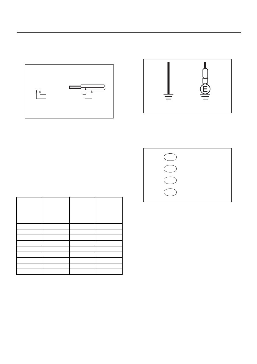
• The wire color code, which consists of two letters
(or three letters including Br or Lg), indicates the
standard color (base color of the wire covering) by
its first letter and the stripe marking by its second
letter.
• The table lists the nominal sectional areas and
allowable currents of the wires.
CAUTION:
When replacing or repairing a wire, be sure to
use the same size and type of the wire which
was originally used.
NOTE:
• The allowable current in the table indicates the
tolerable amperage of each wire at an ambient
temperature of 40
°
C (104
°
F).
• The allowable current changes with ambient
temperature. Also, it changes if a bundle of more
than two wires is used.
• Each unit is directly grounded to the body or indi-
rectly grounds through a harness ground terminal.
Different symbols are used in the wiring diagram to
identify the two grounding systems.
• The ground points shown in the wiring diagram
refer to the following:
NOTE:
All wiring harnesses are provided with a ground
point which should be securely connected.
Nominal
sectional
area
No. of
strands/
strand
diameter
Outside
diameter of
finished
wiring
Allowable
current
Amps/
40
°
C (104
°
F)
mm
2
mm
0.3
7/0.26
1.8
7
0.5
7/0.32
2.2 (or 2.0)
12
0.75
30/0.18
2.6 (or 2.4)
16
0.85
11/0.32
2.4 (or 2.2)
16
1.25
16/0.32
2.7 (or 2.5)
21
2
26/0.32
3.1 (or 2.9)
28
3
41/0.32
3.8 (or 3.6)
38
5
65/0.32
4.6 (or 4.4)
51
8
50/0.45
5.5
67
WI-00111
Black
Marking color :
Y B
Reference color :
Yellow
WI-00112
Direct ground
Indirect terminal
ground
B
WI-01087
GB
GE
GR
GD
: Body ground
: Engine ground
: Radio ground
: Rear defogger ground

WI-8
WIRING SYSTEM
BASIC DIAGNOSTICS PROCEDURE
• Relays are classified as normally-open or normally-closed. The normally-closed relay has one or more
contacts.
The wiring diagram shows the relay mode when the
energizing circuit is OFF.
WI-00114
Relay type
4-pole
6-pole
4-pole
6-pole
Normally-open type
Normally-closed type
Mixed type
Key to symbols:
: Current flows.
: Current does not flow.
Energizing circuit OFF
Energizing circuit ON
WI-9
WIRING SYSTEM
BASIC DIAGNOSTICS PROCEDURE
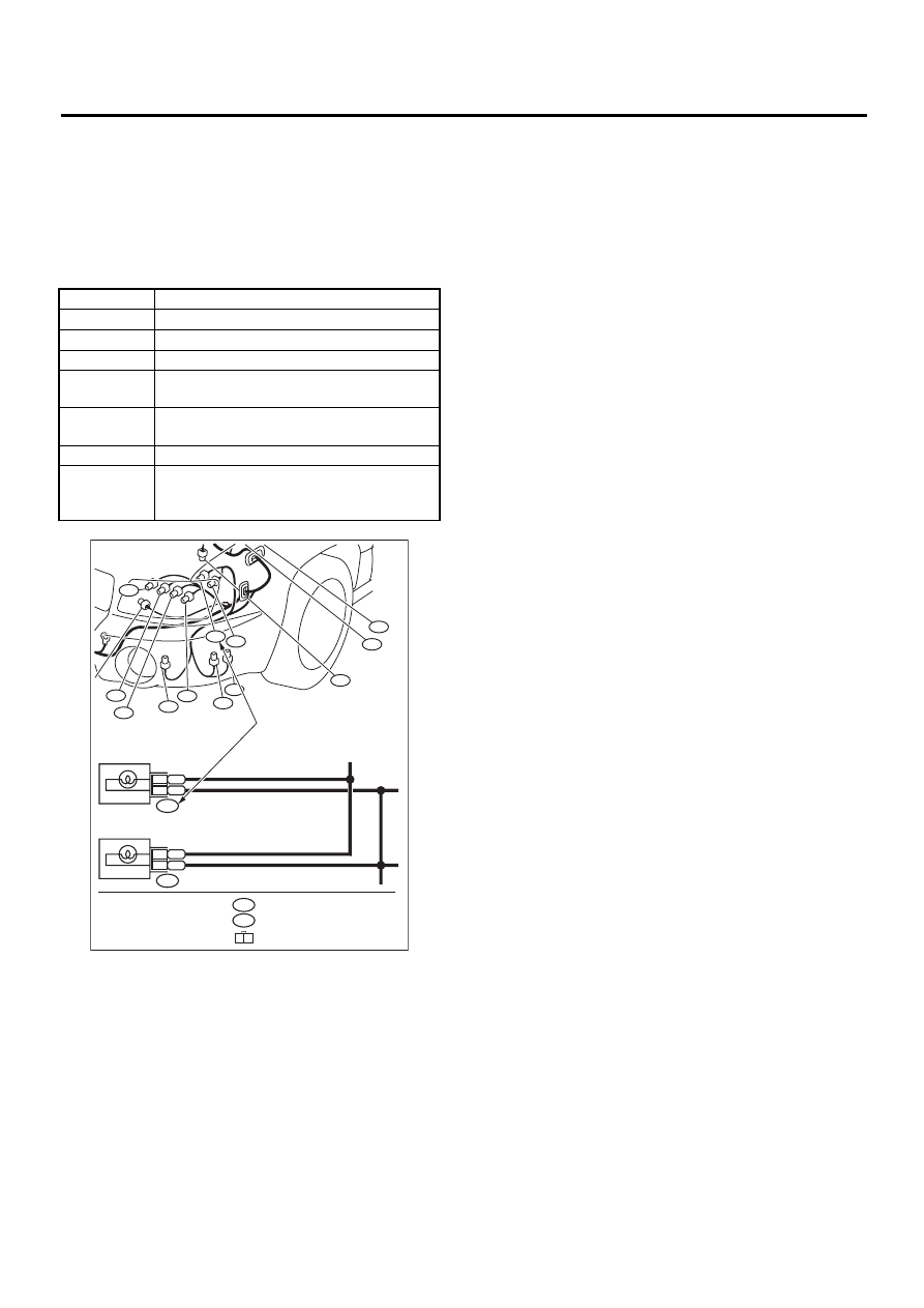
• Each connector number shown in the wiring dia-
gram corresponds to that in the wiring harness. The
location of each connector in the actual vehicle is
determined by reading the first character of the
connector (for example, a “F” for F8, “i” for i16, etc.)
and the type of wiring harness.
The first character of each connector number refers
to the area or system of the vehicle.
Symbol
Wiring harness and cord
F
Front wiring harness
B
Bulkhead wiring harness
E
Engine wiring harness
T
Transmission cord, Rear oxygen sensor
cord
D
Door cord LH & RH,
Rear door cord LH & RH, Rear gate cord
i
Instrument panel wiring harness
R
Rear wiring harness,
Fuel tank cord,
Roof cord
F23
F98
F21
F58
F100
F5
F27
F47
F34
F19
F22
F96
WI-00115
Each connector number
shown in wiring diagram
corresponds to that in
the vehicle.
F19
FRONT TURN SIGNAL
LIGHT LH (UPPER)
BG
2
B
1
F22
FRONT TURN SIGNAL
LIGHT LH (LOWER)
BG
3
B
2
(GRAY)
F3
(GRAY)
F19
1 2
Нет комментариевНе стесняйтесь поделиться с нами вашим ценным мнением.
Текст