Subaru Legacy III (2000-2003 year). Service manual — part 1014
WI-10
WIRING SYSTEM
BASIC DIAGNOSTICS PROCEDURE
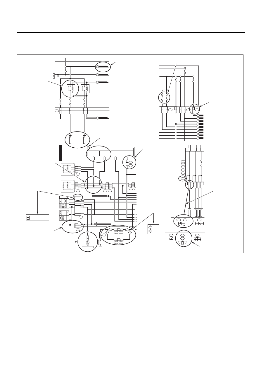
D: SYMBOLS IN WIRING DIAGRAMS
A number of symbols are used in each wiring diagram to easily identify parts or circuits.
1. RELAY
A symbol used to indicate a relay.
2. CONNECTOR-1
The sketch of the connector indicates the one-pole
types.
3. WIRING CONNECTION
Some wiring diagrams are indicated in foldouts for
convenience. Wiring destinations are indicated
where necessary by corresponding symbols (as
when two pages are needed for clear indication).
4. FUSE NO. & RATING
The “FUSE No. & RATING” corresponds with that
used in the fuse box (main fuse box, fuse and joint
box).
5. CONNECTOR-2
• Each connector is indicated by a symbol.
• Each terminal number is indicated in the corre-
sponding wiring diagram in an abbreviated form.
• For example, terminal number “C2” refers to No.
2 terminal of connector (C: F41) shown in the con-
nector sketch.
WI-01088
LR
LW
RL
3
7
2
5
MAIN FUSE BOX (M/B)
MB-11
MB-10
F39
P-SUP-02
B
P-SUP-02
A
P-SUP-02
C
No.3 10A
No.9 15A
No.8 15A
SBF-1 100A
HEAD-
LIGHT
RELAY
RH
HEAD-
LIGHT
RELAY
LH
G
P-SUP-04
D
H/L(2L)-01
RL
LW
GR
LB
MB-10
M/B FUSE NO. 8
MB-11
M/B FUSE NO. 9
FB-16
F/B FUSE NO. 11
(IG)
MB-5
HEADLIGHT
RELAY
TO POWER SUPPLY ROUTING
LW
4
R
3
YL
LW
R
YL
2
YB
1
RY
2
LW
2
R
1
YL
3
P
LW
B1
R
A1
F44
F45
F23
F7
B61
B62
B
REF. TO GND-02
RL
2
R
1
YL
3
B71
B112
LY
8
RY
7
YB
B
17
16
3
17
16
DIMMER & PASSING
SWITCH
UP LOW PASS
HF
HU
HL
E
SMJ
LB
H1
B36
SMJ
DIODE
R4
PARKING BRAKE
SWITCH
LIGHTING SWITCH
OFF
HC
TC
EL
HEADLIGHT LH
LOW
HIGH
HEADLIGHT RH
LOW
HIGH
REF. TO FOG(H4)-01
REF. TO FOG(H6)-01
REF. TO ST(MT)-01
REF. TO ST(AT)-01
B51
A:
B52
C:
F41
G:
FB-37
D4
D7
BG
D11
A2
WR
G4
BL
G1
BR
D10
FB-35
FB-34
1
2 3
4 5 6 7
1 2
3
4 5 6 7 8
LgB
Or
FUSE &
RELAY
BOX (F/B)
i5
B:
B51
A:
B152
D:
B52
C:
B158
E:
F41
G:
F40
F:
FB-36
A3
BG
G7
No.5 10A
(GRAY)
P-SUP-03
H
P-SUP-03
F
P-SUP-04
K
P-SUP-04
J
No.1 20A
No.2 15A
SBF-6 30A
LR
2
R
3
L
1
R
3
BW
2
W
SBF-2 50A
SBF-3 50A
SBF-4 50A
F36
F38
F68
P-SUP-04
E
P-SUP-04
M
P-SUP-04
L
P-SUP-03
I
P-SUP-04
G
1 2 3 4
5 6 7 8
F44
B112
1 2
F23
1
2
3
(BLACK)
F7
(BLACK)
RELAY
DIODE
GROUND
CLASSIFICATION
OF SPECIFICATIONS
CLASSIFICATION
OF SPECIFICATIONS
CONNECTOR-1
CONNECTOR-2
CONNECTOR
SKETCH
FUSE No. & RATING
POWER SUPPLY
ROUTING
SMJ
WIRE TRACING
ON EXTENDED
WIRING DIAGRAMS
SYMBOLS OF
WIRE
CONNECTION
AND CROSSING
Example
: WAGON
WG
P
P
17
SD
SD
WG
WG
R3
B99
P
P
7
R1
B97
2
LY
13
13
WR
OR
: WITHOUT REAR DEFOGGER
: WITH REAR DEFOGGER
OR
WR
: SEDAN
SD
WI-11
WIRING SYSTEM
BASIC DIAGNOSTICS PROCEDURE
6. CONNECTOR SKETCH
• Each connector sketch clearly identifies the
shape and color of a connector as well as terminal
locations. Non-colored connectors are indicated in
natural color.
• When more than two types of connector number
are indicated in a connector sketch, it means that
the same type connectors are used.
7. GROUND
Each grounding point can be located easily by re-
ferring to the corresponding wiring harness.
8. DIODE
A symbol is used to indicate a diode.
9. WIRE TRACING ON EXTENDED WIRING
DIAGRAMS
For a wiring diagram extending over at least two
pages, a symbol (consisting of the same characters
with arrows), facilitates wire tracing from one page
to the next.
A
←→
A, B
←→
B
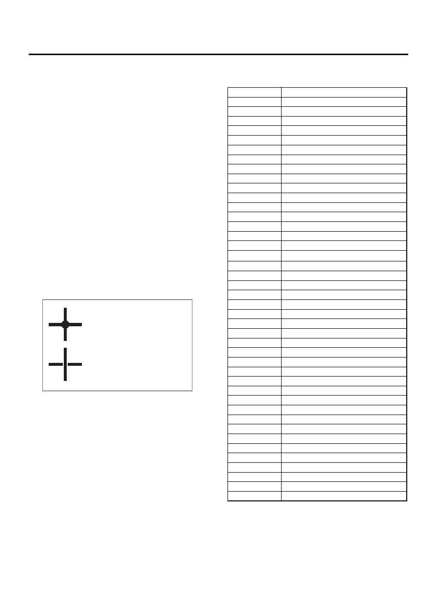
10.SYMBOLS OF WIRE CONNECTION AND
CROSSING
11.POWER SUPPLY ROUTING
A symbol is used to indicate the power supply in
each wiring diagram.
“MB-5”, “MB-6”, etc., which are used as power-
supply symbols throughout the text, correspond
with those shown in the POWER SUPPLY ROUT-
ING in the wiring diagram.
Accordingly, using the POWER SUPPLY ROUT-
ING and wiring diagrams permits service personnel
to understand the entire electrical arrangement of a
system.
E: ABBREVIATION IN WIRING DIA-
GRAMS
WI-00117
Symbol
Symbol
Refers to wires which are
crossed but not connected.
Refers to wires which are
connected and branched
at the dot point.
Abbr.
Full name
ABS
Antilock Brake System
ACC
Accessory
A/C
Air Conditioning
AD
Auto Down
AT
Automatic Transmission
AU
Auto Up
A/B
Air Bag
A/F
Air Fuel
ATF
Automatic Transmission Fluid
AWD
All Wheel Drive
B
Battery
D
Drive Range
DN
Down
E
Ground
ELR
Emergency Locking Retractor
F/B
Fuse & Joint Box
FL1.5
Fusible Link 1.5 mm
2
H/L
Head Light
I/F
Interface
IG
Ignition
Illumi.
Illumination
INT
Intermittent
L/C
Low Clutch
LCD
Liquid Crystal Display
LH
Left Hand
Lo
Low
M
Motor
M/B
Main Fuse Box
MG
Magnet
Mi
Middle
MT
Manual Transmission
N
Neutral Range
OP
Optional Parts
P
Parking Range
PASS
Passing
R
Reverse Range
RH
Right Hand
SBF
Slow Blow Fuse
ST
Starter
SW
Switch
UP
Up
WASH
Washer
WI-12
WIRING SYSTEM
WORKING PRECAUTIONS
2. Working Precautions
A: PRECAUTIONS WHEN WORKING
WITH THE PARTS MOUNTED ON
THE VEHICLE
1) When working under a vehicle which is jacked-
up, always be sure to use safety stands.
2) The parking brake must always be applied dur-
ing working. Also, in automatic transmission vehi-
cles, keep the select lever set to the P (Parking)
range.
3) Be sure the workshop is properly ventilated
when running the engine. Further, be careful not to
touch the belt or fan while the engine is operating.
4) Be careful not to touch hot metal parts, especial-
ly the radiator and exhaust system immediately af-
ter the engine has been shut off.
B: PRECAUTIONS IN TROUBLE DI-
AGNOSIS AND REPAIR OF ELEC-
TRIC PARTS
1) The battery cable must be disconnected from
the battery's (
−
) terminal, and the ignition switch
must be set to the OFF position, unless otherwise
required by the diagnostics.
2) Securely fasten the wiring harness with clamps
and slips so that the harness does not interfere with
the body end parts or edges and bolts or screws.
3) When installing parts, be careful not to catch
them on the wiring harness.
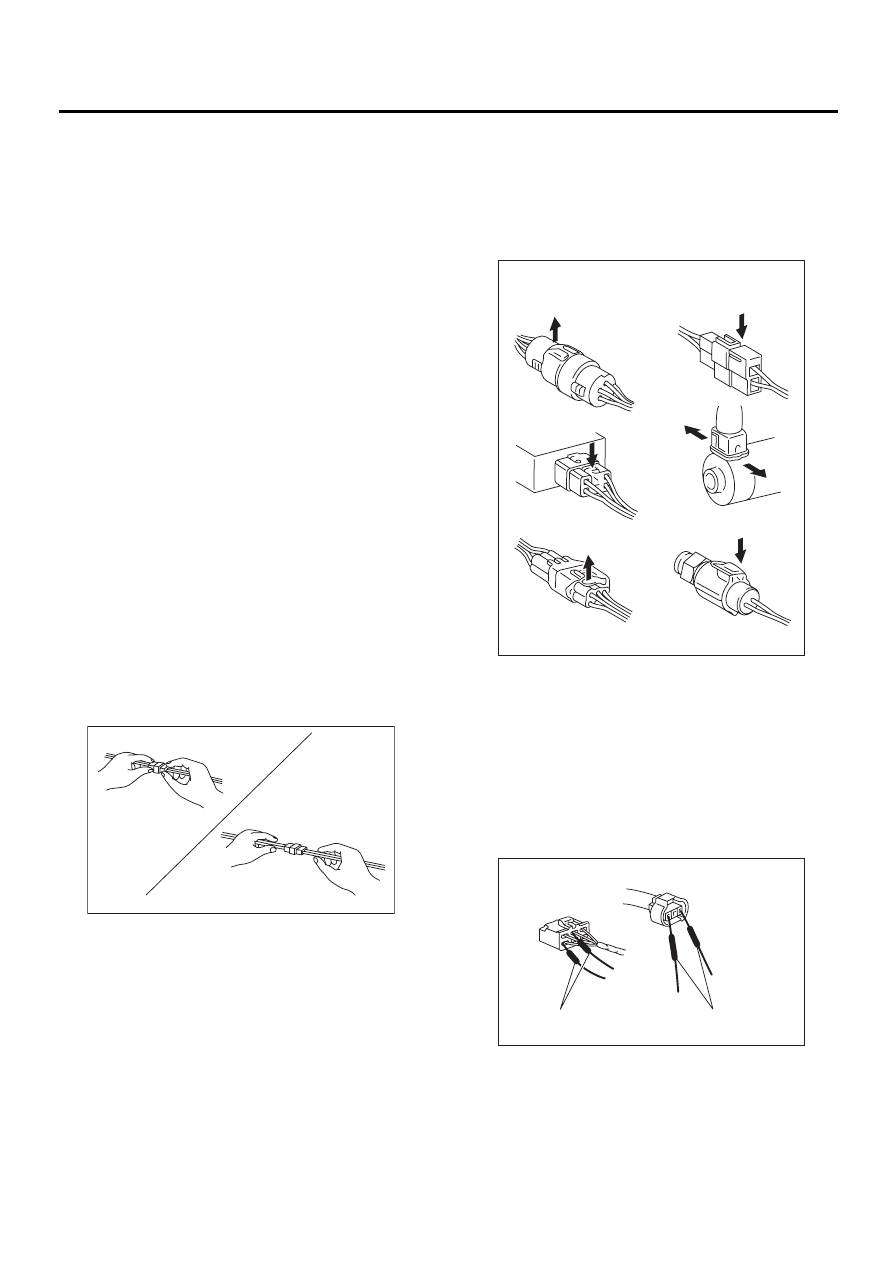
4) When disconnecting a connector, do not pull the
wires, but pull while holding the connector body.
5) Some connectors are provided with a lock. One
type of such a connector is disconnected by push-
ing the lock, and the other, by moving the lock up.
In either type the lock shape must be identified be-
fore attempting to disconnect the connector.
To connect, insert the connector until it snaps and
confirm that it is tightly connected.
6) When checking continuity between connector
terminals, or measuring voltage across the terminal
and ground, always contact tester probe(s) on ter-
minals from the wiring connection side. If the probe
is too thick to gain access to the terminal, use “mini”
test leads.
To check water-proof connectors (which are not ac-
cessible from the wiring side), contact test probes
on the terminal side being careful not to bend or
damage the terminals.
7) Sensors, relays, electrical unit, etc., are sensi-
tive to strong impacts.
Handle them with care so that they are not dropped
or mishandled.
WI-00118
Correct
Wrong
WI-00119
Example
LIFT
LIFT
PUSH
PUSH
PUSH
WI-00120
Tester probes
"Mini" test leads
WI-13
WIRING SYSTEM
SUPER MULTIPLE JUNCTION (SMJ)
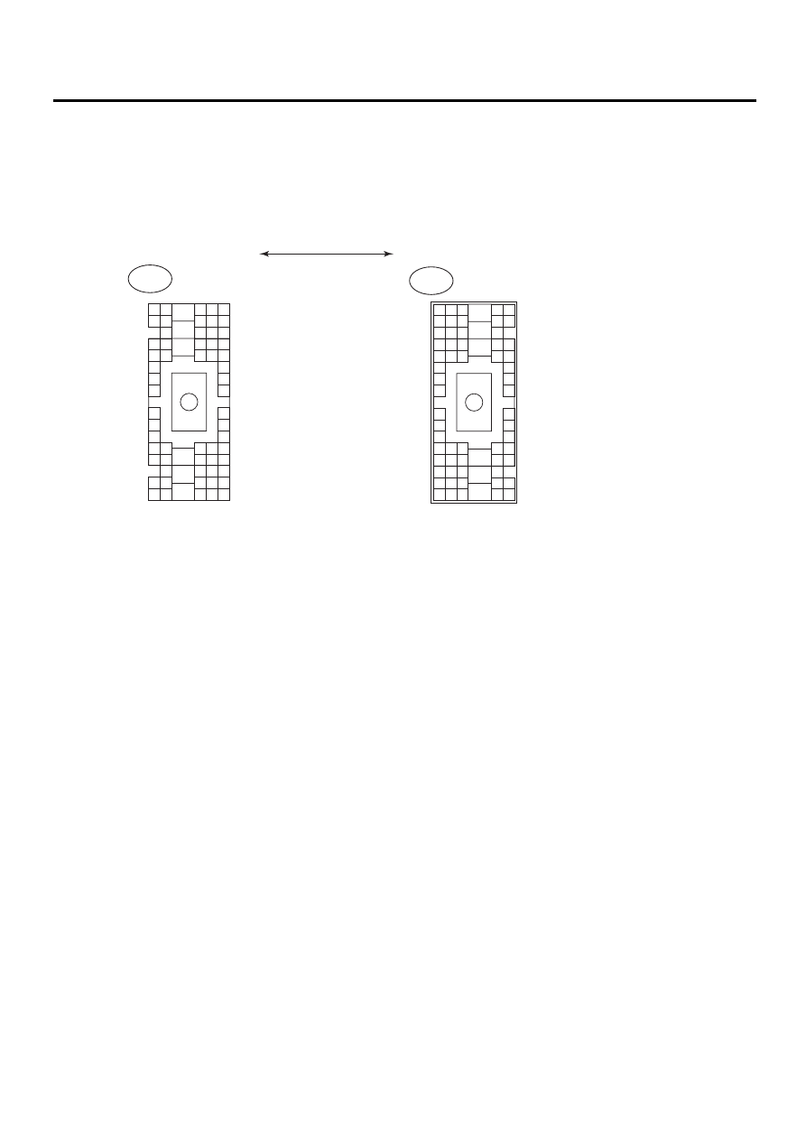
3. Super Multiple Junction (SMJ)
A: HOW TO USE SUPER MULTIPLE JUNCTION (SMJ)
The “SMJ” indicated in wiring diagrams is shown in a simplified form.
B: TERMINAL ARRANGEMENT
WI-01078
B36
i1
66 Poles
66 Poles
B4 B5 B6
A4 A5 A6
C5 C6
F6
D4 D5 D6
F1
H1
C4
G6
G1
C2
K1
M1 M2
K6
L1
D1 D2
A1 A2
B1 B2
I6
J6
L2
I1
J1
H6
M4 M5 M6
L4 L5 L6
N5 N6
O4 O5 O6
N4
P4 P5
N2
O1 O2
P1 P2
N3
O3
P3
P6
A3
B3
C3
E4 E5 E6
E1 E2
B4
B5
B6
A4
A5
A6
C5
C6
F6
D4
D5
D6
F1
H1
C4
G6
G1
C2
K1
M1
M2
K6
L1
D1
D2
A1
A2
B1
B2
I6
J6
L2
I1
J1
H6
M4
M5
M6
L4
L5
L6
N5
N6
O4
O5
O6
N4
P4
P5
N2
O1
O2
P1
P2
N3
O3
P3
P6
A3
B3
C3
E4
E5
E6
E1
E2
Instrument Panel Wiring Harness
Bulkhead Wiring Harness
Нет комментариевНе стесняйтесь поделиться с нами вашим ценным мнением.
Текст