Subaru Legacy III (2000-2003 year). Service manual — part 1012
WI-2
WIRING SYSTEM
Sunroof System. . . . . . . . . . . . . . . . . . . . . ...306
Vehicle Dynamic Control System . . . . . . . . . . . . . . . 308
Wiper and Washer System (Front). . . . . . . . . . . . . . ..324
Wiper and Washer System (Rear) . . . . . . . . . . . . . . ..326
Wiper Deicer System . . . . . . . . . . . . . . . . . . . ..328
Harness components location. . . . . . . . . . . . . . . . .330
Front Wiring Harness . . . . . . . . . . . . . . . . . . . ..334
Bulkhead Wiring Harness (In Engine Room) . . . . . . . . . . ..338
Bulkhead Wiring Harness (In Compartment) . . . . . . . . . . ..346
Engine Wiring Harness and Transmission Cord . . . . . . . . . .360
Instrument Panel Wiring Harness . . . . . . . . . . . . . . ...366
Rear Wiring Harness . . . . . . . . . . . . . . . . . . . ...370
Door Cord. . . . . . . . . . . . . . . . . . . . . . . . 378
Rear Wiring Harness and Trunk Lid Cord . . . . . . . . . . . ...382
Rear Wiring Harness and Rear Gate Cord . . . . . . . . . . . .384
WI-3
WIRING SYSTEM
BASIC DIAGNOSTICS PROCEDURE
1. Basic Diagnostics Procedure
A: BASIC PROCEDURES
1. GENERAL
The most important purpose of diagnostics is to de-
termine which part is malfunctioning quickly, to
save time and labor.
2. IDENTIFICATION OF TROUBLE SYMP-
TOM
Determine what the problem is based on the symp-
tom.
3. PROBABLE CAUSE OF TROUBLE
Look at the wiring diagram and check the system's
circuit. Then check the switch, relay, fuse, ground,
etc.
4. LOCATION AND REPAIR OF TROUBLE
1) Using the diagnostics narrow down the causes.
2) If necessary, use a voltmeter, ohmmeter, etc.
3) Before replacing certain component parts
(switch, relay, etc.), check the power supply,
ground, for open wiring harness, poor connectors,
etc. If no problems are encountered, check the
component parts.
5. CONFIRMATION OF SYSTEM OPERA-
TION
After repairing, ensure that the system operates
properly.
B: BASIC INSPECTION
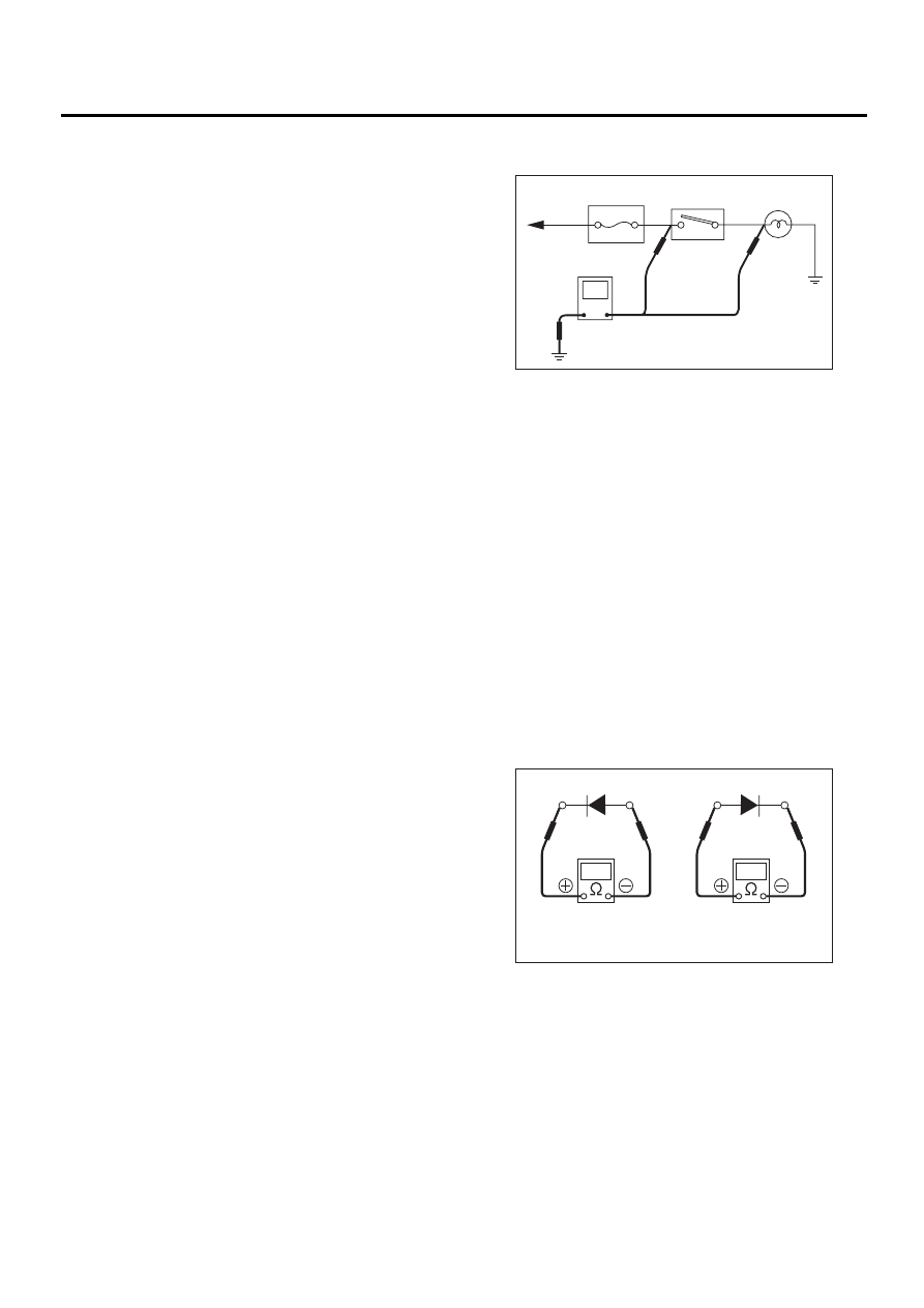
1. VOLTAGE MEASUREMENT
1) Using a voltmeter, connect the negative lead to a
good ground point or negative battery terminal and
the positive lead to the connector or component ter-
minal.
2) Contact the positive probe of the voltmeter on
connector (A).
The voltmeter will indicate a voltage.
3) Shift the positive probe to connector (B). The
voltmeter will indicate no voltage.
4) With test set-up held as it is, turn switch ON. The
voltmeter will indicate a voltage and, at the same
time, the light will come on.
5) The circuit is in good order. If a problem such as
a lamp failing to light occurs, use the procedures
outlined above to track down the malfunction.
2. CIRCUIT CONTINUITY CHECKS
1) Disconnect the battery terminal or connector so
there is no voltage between the check points.
Contact the two leads of an ohmmeter to each of
the check points.
If the circuit has diodes, reverse the two leads and
check again.
2) Use an ohmmeter to check for diode continuity.
When contacting the negative lead to the diode
positive side and the positive lead to the negative
side, there should be continuity.
When contacting the two leads in reverse, there
should be no continuity.
WI-00094
To power
FUSE
supply
Switch
Light
V
(A)
(B)
WI-00095
Continuity
No continuity
WI-4
WIRING SYSTEM
BASIC DIAGNOSTICS PROCEDURE
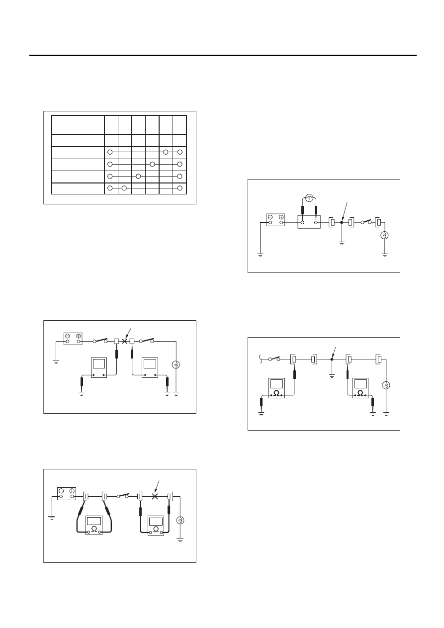
3) Symbol “
❍
—
❍
” indicates that continuity exists
between two points or terminals. For example,
when a switch position is “3”, continuity exists
among terminals 1, 3 and 6, as shown in table be-
low.
3. HOW TO DETERMINE AN OPEN CIR-
CUIT
1) Voltmeter Method:
An open circuit is determined by measuring the
voltage between respective connectors and ground
using a voltmeter, starting with the connector clos-
est to the power supply. The power supply must be
turned ON so that current flows in the circuit. If volt-
age is not present between a particular connector
and ground, the circuit between that connector and
the previous connector is open.
2) Ohmmeter method:
Disconnect all connectors affected, and check con-
tinuity in the wiring between adjacent connectors.
When the ohmmeter indicates “infinite”, the wiring
is open.
4. HOW TO DETERMINE A SHORT CIR-
CUIT
1) Test lamp method:
Connect a test lamp (rated at approximately 3
watts) in place of the blown fuse and allow current
to flow through the circuit. Disconnect one connec-
tor at a time from the circuit, starting with the one lo-
cated farthest from the power supply. If the test
lamp goes out when a connector is disconnected,
the wiring between that connection and the next
connector (farther from the power supply) is short-
ed.
2) Ohmmeter method:
Disconnect all affected connectors, and check
continuity between each connector and ground.
When ohmmeter indicates continuity between a
particular connector and ground, that connector is
shorted.
WI-00096
Terminal
Switch Position
OFF
1
2
3
4
1
2
3
4
5
6
WI-00097
Open circuit or wiring
No voltage is present
Voltage is present
V
V
WI-00098
Open circuit
Continuity does not exist.
Continuity exists.
WI-00099
Shorted wiring
Test lamp
Fuse holder
WI-00100
Shorted connector
Continuity does not exist.
Continuity exists.
WI-5
WIRING SYSTEM
BASIC DIAGNOSTICS PROCEDURE
C: HOW TO READ WIRING DIA-
GRAMS
1. WIRING DIAGRAM
The wiring diagram of each system is illustrated so that you can understand the path through which the elec-
tric current flows from the battery.
Sketches and codes are used in the diagrams. They should read as follows:
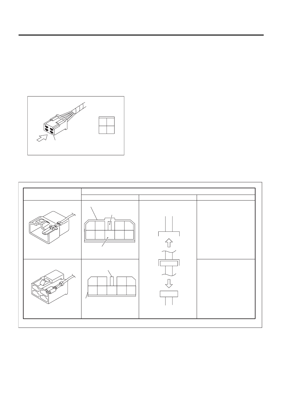
• Each connector and its terminal position are indicated by a sketch of the connector in a disconnected state
which is viewed from the front.
• The number of poles or pins, presence of a lock, and pin number of each terminal are indicated in the
sketch of each connector. In the sketch, the highest pole number refers to the number of poles which the con-
nector has. For example, the sketch of the connector shown in figure indicates the connector has 9 poles.
WI-00101
Viewed from this direction
4
2
4
1
3
WI-00102
Connector used in vehicle
Sketch
Symbol
Number of poles
Numbered in order from upper
right to lower left.
Numbered in order from upper
left to lower right
Connector shown in wiring diagram
Double frames
Indicates a lock
is included.
Indicates the number of poles.
4
3
2
1
9
8
7
6
5
Indicates a lock is included.
Single frame
1
2
3
4
5
6
7
8
9
Нет комментариевНе стесняйтесь поделиться с нами вашим ценным мнением.
Текст