Subaru Legacy III (2000-2003 year). Service manual — part 220
EN(H4SOw/oOBD)-70
ENGINE (DIAGNOSTICS)
DIAGNOSTIC PROCEDURE WITH DIAGNOSTIC TROUBLE CODE (DTC)
7
CHECK ENGINE COOLANT TEMPERATURE
SENSOR.
1) Raise temperature up to approx. 90
°
C
(194
°
F).
CAUTION:
Be careful not to burn yourself.
2) Measure resistance between engine cool-
ant temperature sensor terminals.
Terminals
No. 1 — No. 2:
Is the measured value within the specified
value?
0.2 — 0.3 k
Ω
Replace ECM.
Replace engine
coolant tempera-
ture sensor.
Step
Value
Yes
No
EN(H4SOw/oOBD)-71
ENGINE (DIAGNOSTICS)
DIAGNOSTIC PROCEDURE WITH DIAGNOSTIC TROUBLE CODE (DTC)
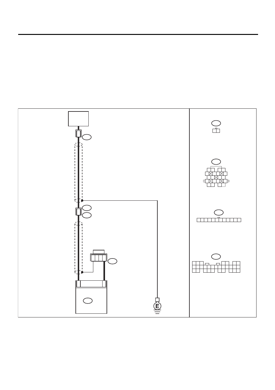
E: DTC 22 KNOCK SENSOR
• DIAGNOSIS:
• The knock sensor signal is abnormal.
• The harness connector between ECM and knock sensor is in short or open.
• TROUBLE SYMPTOM:
• Poor driving performance
CAUTION:
After repair or replacement of faulty parts, conduct CLEAR MEMORY and INSPECTION MODES. <Ref.
to EN(H4SOw/oOBD)-28, OPERATION, Clear Memory Mode.> and <Ref. to EN(H4SOw/oOBD)-26, OP-
ERATION, Inspection Mode.>
• WIRING DIAGRAM:
EN-01053
4
25
KNOCK
SENSOR
16
2
2
3
5
4
6 7
8
2
1
9
3
10
22
23
11 12 13 14 15
24 25
26 27
16 17 18
28 29
19 20
21
30
B136
ECM
B136
B83
B21
E2
E14
B83
B21
E14
1 2
1 2
5
6 7
8
13
14 15
16
9 10
11 12
3 4
17 18
19 20
1 2 3 4 5 6 7 8 9 10 11 12

EN(H4SOw/oOBD)-72
ENGINE (DIAGNOSTICS)
DIAGNOSTIC PROCEDURE WITH DIAGNOSTIC TROUBLE CODE (DTC)
Step
Value
Yes
No
1
CHECK INPUT SIGNAL FOR ECM.
1) Turn ignition switch to ON.
2) Measure voltage between ECM connector
and chassis ground.
Connector & terminal
(B136) No. 4 (+) — Chassis ground (–):
Does the measured value exceed the spec-
ified value?
3 V
2
CHECK POOR CONTACT.
Check poor contact in ECM connector.
Is there poor contact in ECM connector?
There is poor contact.
Repair poor con-
tact in ECM con-
nector.
Replace ECM.
<Ref. to
FU(H4SOw/
oOBD)-42, Engine
Control Module.>
3
CHECK KNOCK SENSOR.
1) Disconnect connector from knock sensor.
2) Measure resistance between knock sensor
connector terminal and engine ground.
Terminal
No. 2 — Engine ground:
Is the measured value within the specified
value?
530 k
Ω
— 590 k
Ω
Replace knock
sensor. <Ref. to
FU(w/oOBD)-,
Knock Sensor.>
4
CHECK HARNESS CONNECTOR BETWEEN
ECM AND KNOCK SENSOR.
1) Remove ECM connector.
2) Measure resistance of harness connector
between ECM and knock sensor.
Connector & terminal
(E14) No. 2 — (B136) No. 4:
Is the measured value less than the speci-
fied value?
1
Ω
Repair harness
and connector.
NOTE:
In this case, repair
the following:
• Open circuit in
harness between
knock sensor and
ECM connector
• Poor contact in
knock sensor con-
nector
• Poor contact in
coupling connector
(B21)
5
CHECK HARNESS CONNECTOR BETWEEN
ECM AND KNOCK SENSOR.
Measure resistance of harness of harness con-
nector between ECM connector and knock
sensor.
Connector & terminal
(B136) No. 4 — Chassis ground:
Does the measured value exceed the specified
value?
1 M
Ω
Repair ground
short circuit
between ECM and
knock sensor.
6
CHECK POOR CONTACT.
Check poor contact in ECM connector.
Is there poor contact in ECM connector?
There is poor contact.
Repair poor con-
tact in ECM con-
nector.
Replace ECM.
<Ref. to
FU(H4SOw/
oOBD)-42, Engine
Control Module.>
EN(H4SOw/oOBD)-73
ENGINE (DIAGNOSTICS)
DIAGNOSTIC PROCEDURE WITH DIAGNOSTIC TROUBLE CODE (DTC)
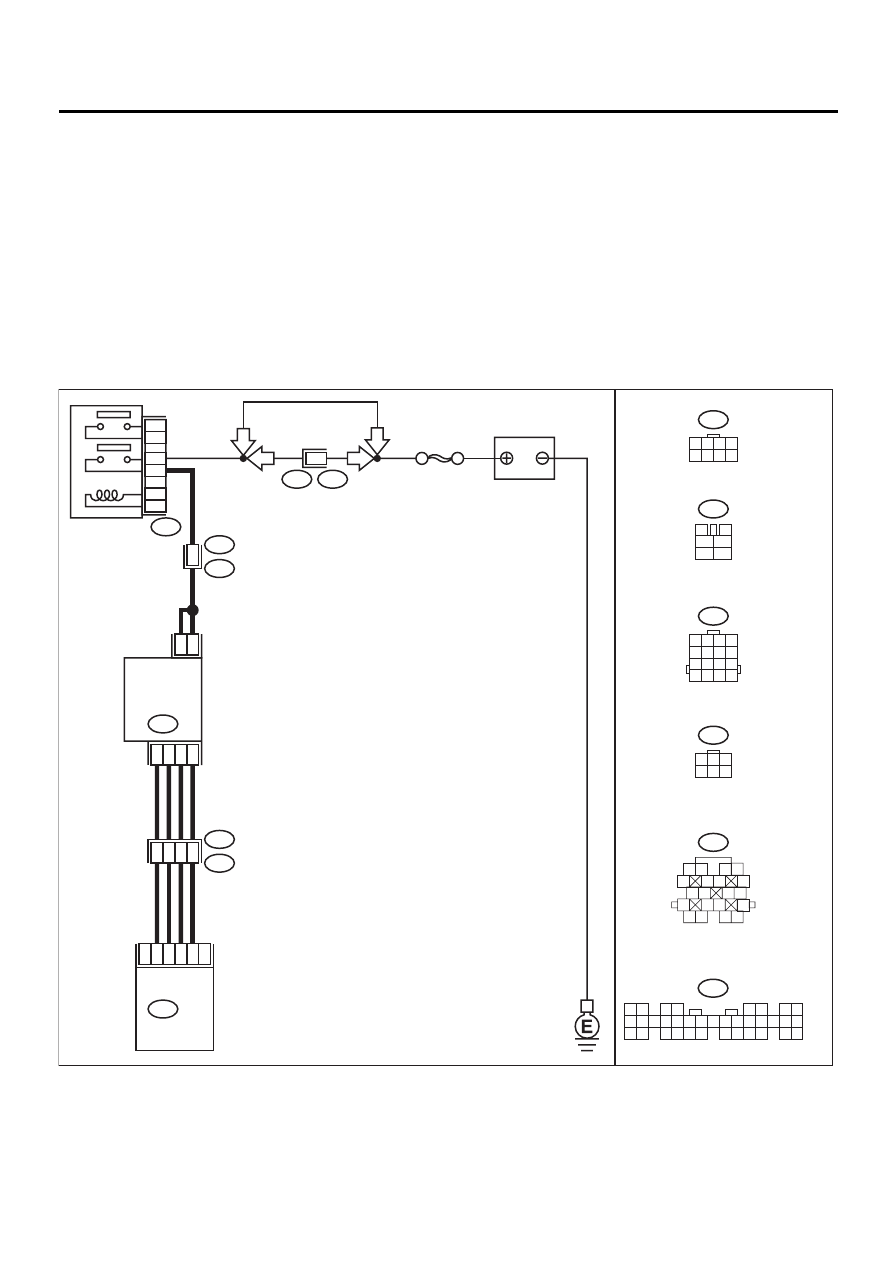
F: DTC 24 IDLE AIR CONTROL SOLENOID VALVE
• DIAGNOSIS:
• The idle air control solenoid valve is not in function.
• The harness connector between ECM and idle air control solenoid valve is in short or open.
• TROUBLE SYMPTOM:
• Erroneous idling
• Hard to start
• Poor driving performance
CAUTION:
After repair or replacement of faulty parts, conduct CLEAR MEMORY and INSPECTION MODES. <Ref.
to EN(H4SOw/oOBD)-28, OPERATION, Clear Memory Mode.> and <Ref. to EN(H4SOw/oOBD)-26, OP-
ERATION, Inspection Mode.>
• WIRING DIAGRAM:
EN-01054
5
6
19
20
B21
E2
F44
B61
ECM
2
5
6
3
4
1
3
4
1
2
IDLE
AIR CONTROL
SOLENOID
VALVE
E7
B22
E3
B47
B134
B47
3
4
1
2
5
6
B134
1 2
3 4
5 6
7 8
9 10 11 12 13 14 15 16 17 18 19 20 21 22 23
24 25
26 27 28 29
30 31 32 33
34 35
B22
1 2 3 4
5 6 7 8
9 10 11 12
13 14 15 16
E7
1
3
4 5 6
2
B21
1 2
3 4
5
6 7
8
9 10
11 12
13
14 15
16
17 18
19 20
SBF-5
BATTERY
MAIN RELAY
1
2
3
5
4
6
1
6
LHD
LHD
RHD
RHD
1 2 3 4
5 6 7 8
F44
Нет комментариевНе стесняйтесь поделиться с нами вашим ценным мнением.
Текст