Subaru Legacy III (2000-2003 year). Service manual — part 723
ABS-110
ABS (DIAGNOSTICS)
DIAGNOSTICS CHART WITH SUBARU SELECT MONITOR
S: DTC 38 REAR LEFT OUTLET VALVE MALFUNCTION
DIAGNOSIS:
• Faulty harness/connector
• Faulty outlet solenoid valve
TROUBLE SYMPTOM:
• ABS does not operate.
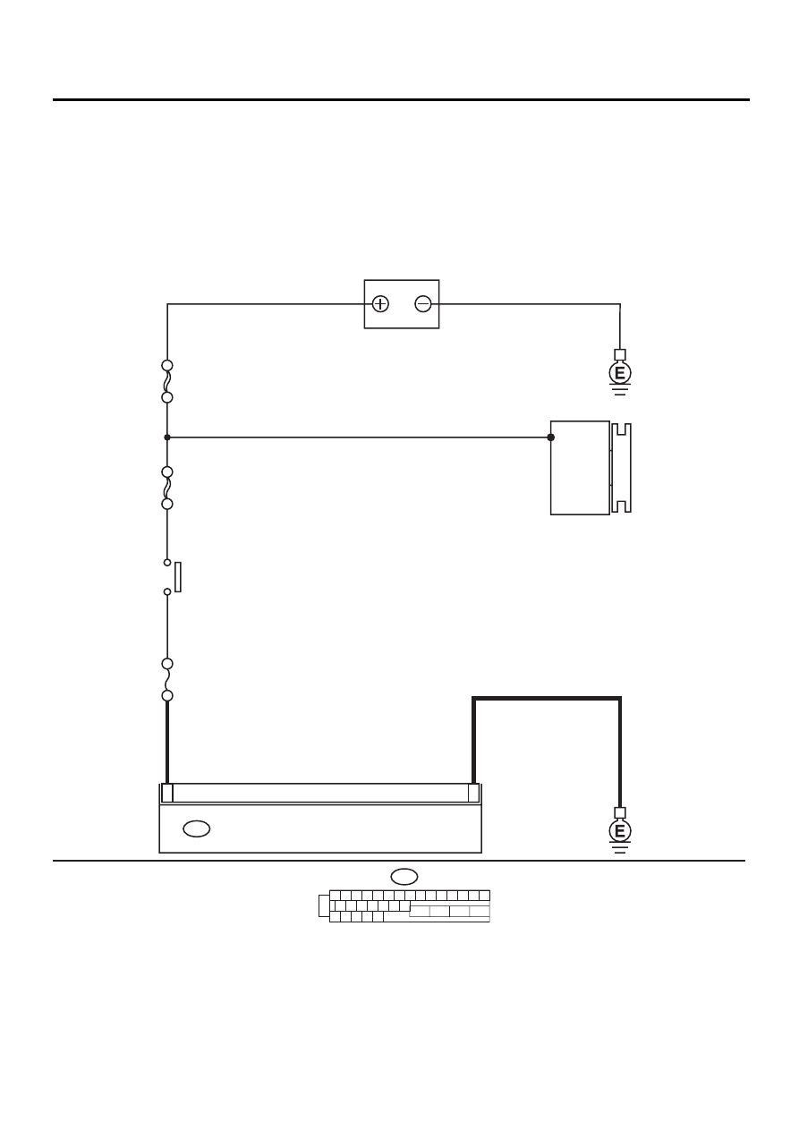
WIRING DIAGRAM:
ABS00294
1
23
ABS CONTROL MODULE AND HYDRAULIC CONTROL UNIT
F49
1 2 3 4 5 6 7 8 9 10 11 12 13 14 15
16 17 18 19 20 21 22
27 28 29 30 31
23
24
25
26
F49
BATTERY
NO
. 18 15A
SBF-4 50A
SBF-1 100A
GENERATOR
IGNITION
SWITCH

ABS-111
ABS (DIAGNOSTICS)
DIAGNOSTICS CHART WITH SUBARU SELECT MONITOR
Step
Value
Yes
No
1
CHECK INPUT VOLTAGE OF ABSCM&H/U.
1) Turn ignition switch to OFF.
2) Disconnect connector from ABSCM&H/U.
3) Run the engine at idle.
4) Measure voltage between ABSCM&H/U
connector and chassis ground.
Connector & terminal
(F49) No. 1 (+) — Chassis ground (
−−−−
):
Is the measured value within the specified
range?
10 - 15 V
Repair harness
connector
between battery,
ignition switch and
ABSCM&H/U.
2
CHECK GROUND CIRCUIT OF ABSCM&H/U.
1) Turn ignition switch to OFF.
2) Measure resistance between ABSCM&H/U
connector and chassis ground.
Connector & terminal
(F49) No. 23 — Chassis ground:
Is the measured value less than the speci-
fied value?
0.5
Ω
Repair
ABSCM&H/U
ground harness.
3
CHECK POOR CONTACT IN CONNECTORS.
Is there poor contact in connectors between
generator, battery and ABSCM&H/U?
There is no poor contact.
Repair connector.
4
CHECK ABSCM&H/U.
1) Connect all connectors.
2) Erase the memory.
3) Perform inspection mode.
4) Read out the DTC.
Is the same DTC as in the current diagno-
sis still being output?
Same DTC is not indicated.
Replace
ABSCM&H/U.
<Ref. to ABS-6,
ABS Control Mod-
ule and Hydraulic
Control Unit
(ABSCM&H/U).>
5
CHECK ANY OTHER DTC APPEARANCE.
Are other DTC being output?
Other DTC is not indicated.
A temporary poor
contact.
Proceed with the
diagnosis corre-
sponding to the
DTC.
ABS-112
ABS (DIAGNOSTICS)
DIAGNOSTICS CHART WITH SUBARU SELECT MONITOR
T: DTC 41 ABS CONTROL MODULE MALFUNCTION
DIAGNOSIS:
• Faulty ABSCM&H/U
TROUBLE SYMPTOM:
• ABS does not operate.
WIRING DIAGRAM:
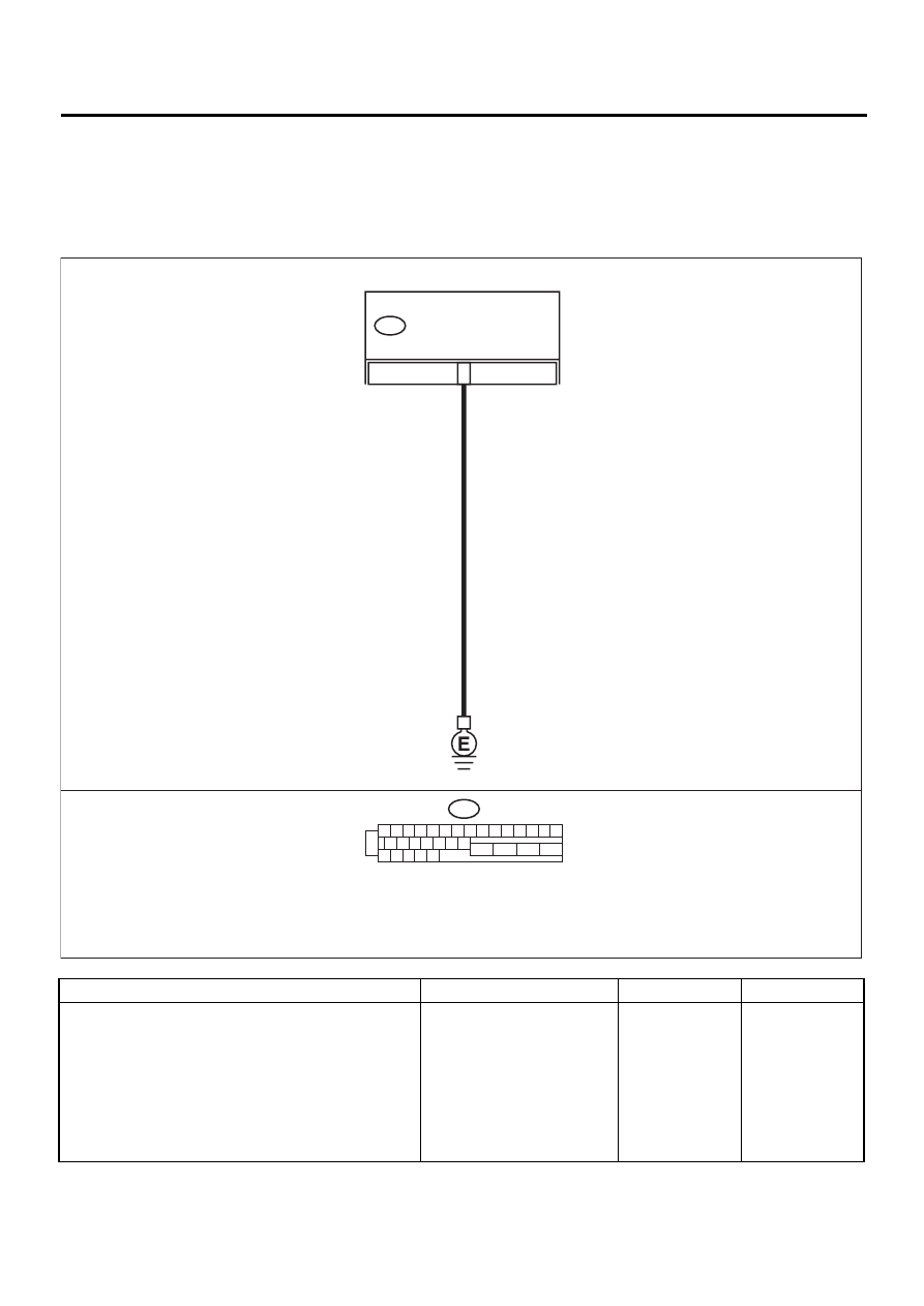
Step
Value
Yes
No
1
CHECK GROUND CIRCUIT OF ABSCM&H/U.
1) Turn ignition switch to OFF.
2) Disconnect connector from ABSCM&H/U.
3) Measure resistance between ABSCM&H/U
and chassis ground.
Connector & terminal
(F49) No. 23 — Chassis ground:
Is the measured value less than the speci-
fied value?
0.5
Ω
Repair
ABSCM&H/U
ground harness.
1 2 3 4 5 6 7 8 9 10 11 12 13 14 15
16 17 18 19 20 21 22
27 28 29 30 31
23
24
25
26
F49
23
ABS CONTROL MODULE AND
HYDRAULIC CONTROL UNIT
F49
ABS00295

ABS-113
ABS (DIAGNOSTICS)
DIAGNOSTICS CHART WITH SUBARU SELECT MONITOR
2
CHECK POOR CONTACT IN CONNECTORS.
Is there poor contact in connectors between
battery, ignition switch and ABSCM&H/U?
There is no poor contact.
Repair connector.
3
CHECK SOURCES OF SIGNAL NOISE.
Is the car telephone or the wireless transmitter
properly installed?
Installed properly.
Properly install the
car telephone or
the wireless trans-
mitter.
4
CHECK SOURCES OF SIGNAL NOISE.
Are noise sources (such as an antenna)
installed near the sensor harness?
Noise source is not installed
near the sensor harness.
Install the noise
sources apart from
the sensor har-
ness.
5
CHECK ABSCM&H/U.
1) Turn ignition switch to OFF.
2) Connect all connectors.
3) Erase the memory.
4) Perform inspection mode.
5) Read out the DTC.
Is the same DTC as in the current diagno-
sis still being output?
Same DTC is not indicated.
Replace
ABSCM&H/U.
<Ref. to ABS-6,
ABS Control Mod-
ule and Hydraulic
Control Unit
(ABSCM&H/U).>
6
CHECK ANY OTHER DTC APPEARANCE.
Are other DTC being output?
Other DTC is not indicated.
A temporary poor
contact.
Proceed with the
diagnosis corre-
sponding to the
DTC.
Step
Value
Yes
No
Нет комментариевНе стесняйтесь поделиться с нами вашим ценным мнением.
Текст