Subaru Legacy III (2000-2003 year). Service manual — part 724
ABS-114
ABS (DIAGNOSTICS)
DIAGNOSTICS CHART WITH SUBARU SELECT MONITOR
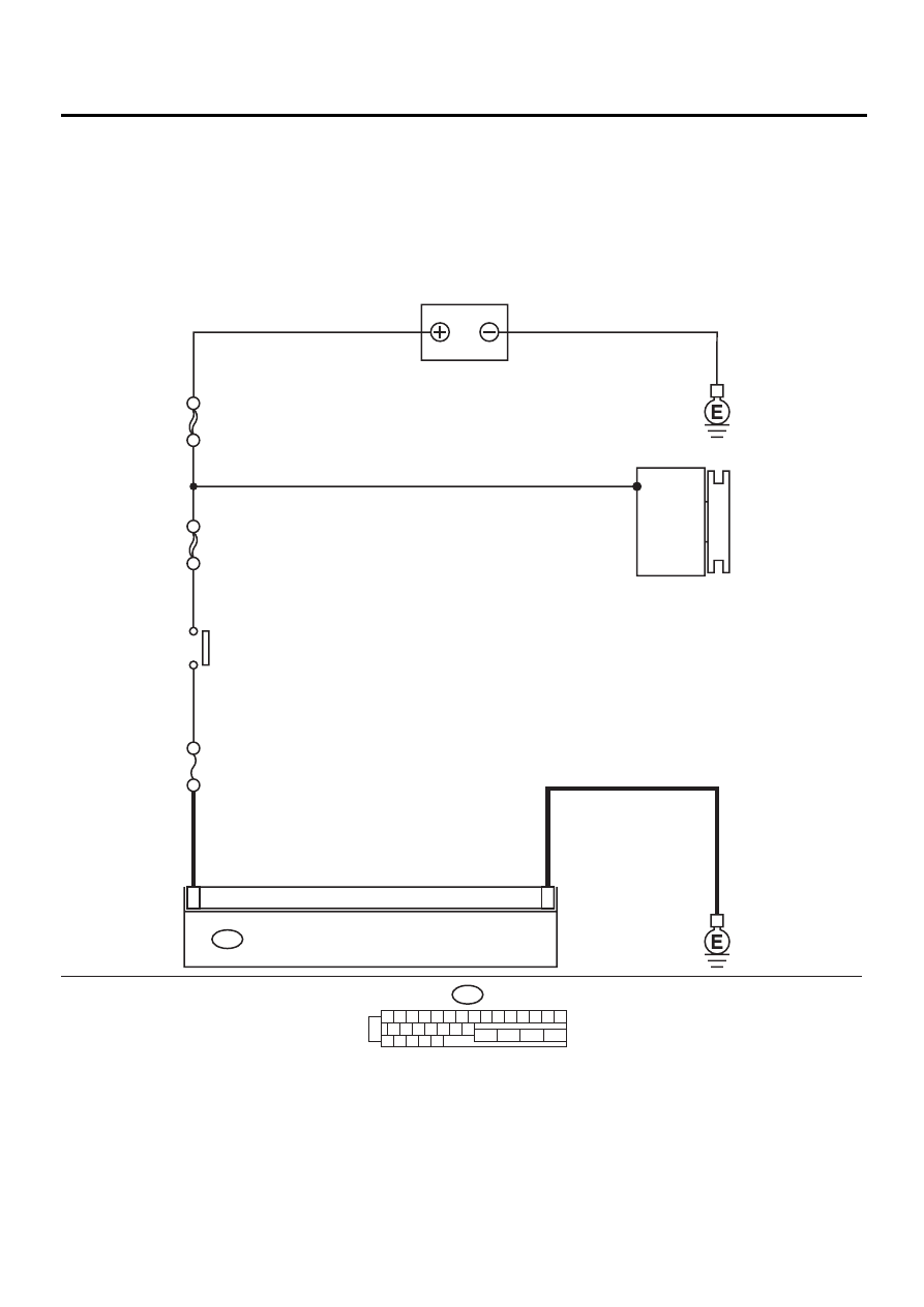
U: DTC 42 POWER SUPPLY VOLTAGE TOO LOW
DIAGNOSIS:
• Power source voltage of the ABSCM&H/U is low.
TROUBLE SYMPTOM:
• ABS does not operate.
WIRING DIAGRAM:
ABS00294
1
23
ABS CONTROL MODULE AND HYDRAULIC CONTROL UNIT
F49
1 2 3 4 5 6 7 8 9 10 11 12 13 14 15
16 17 18 19 20 21 22
27 28 29 30 31
23
24
25
26
F49
BATTERY
NO
. 18 15A
SBF-4 50A
SBF-1 100A
GENERATOR
IGNITION
SWITCH

ABS-115
ABS (DIAGNOSTICS)
DIAGNOSTICS CHART WITH SUBARU SELECT MONITOR
Step
Value
Yes
No
1
CHECK GENERATOR.
1) Start engine.
2) Idling after warm-up.
3) Measure voltage between generator B ter-
minal and chassis ground.
Terminal
Generator B terminal — Chassis
ground:
Is the measured value within the specified
range?
10 - 15 V
i) Repair genera-
tor.
ii) H4 engine
model:
iii) <Ref. to
SC(H4SO)-14,
Generator.>
iv) H6 engine
model:
v) <Ref. to
SC(H6DO)-14,
Generator.>
2
CHECK BATTERY TERMINAL.
Turn ignition switch to OFF.
Are the positive and negative battery terminals
tightly clamped?
Terminals are tightened
securely.
Tighten the clamp
of terminal.
3
CHECK INPUT VOLTAGE OF ABSCM&H/U.
1) Disconnect connector from ABSCM&H/U.
2) Run the engine at idle.
3) Measure voltage between ABSCM&H/U
connector and chassis ground.
Connector & terminal
(F49) No. 1 (+) — Chassis ground (
−−−−
):
Is the measured value within the specified
range?
10 - 15 V
Repair harness
connector
between battery,
ignition switch and
ABSCM&H/U.
4
CHECK GROUND CIRCUIT OF ABSCM&H/U.
1) Turn ignition switch to OFF.
2) Measure resistance between ABSCM&H/U
connector and chassis ground.
Connector & terminal
(F49) No. 23 — Chassis ground:
Is the measured value less than the speci-
fied value?
0.5
Ω
Repair
ABSCM&H/U
ground harness.
5
CHECK POOR CONTACT IN CONNECTORS.
Is there poor contact in connectors between
generator, battery and ABSCM&H/U?
There is no poor contact.
Repair connector.
6
CHECK ABSCM&H/U.
1) Connect all connectors.
2) Erase the memory.
3) Perform inspection mode.
4) Read out the DTC.
Is the same DTC still being output?
Same DTC is not indicated.
Replace
ABSCM&H/U.
<Ref. to ABS-6,
ABS Control Mod-
ule and Hydraulic
Control Unit
(ABSCM&H/U).>
7
CHECK ANY OTHER DTC APPEARANCE.
Are other DTC being output?
Other DTC is not indicated.
A temporary poor
contact.
Proceed with the
diagnosis corre-
sponding to the
DTC.

ABS-116
ABS (DIAGNOSTICS)
DIAGNOSTICS CHART WITH SUBARU SELECT MONITOR
V: DTC 42 POWER SUPPLY VOLTAGE TOO HIGH
DIAGNOSIS:
• Power source voltage of the ABSCM&H/U is high.
TROUBLE SYMPTOM:
• ABS does not operate.
WIRING DIAGRAM:
ABS00294
1
23
ABS CONTROL MODULE AND HYDRAULIC CONTROL UNIT
F49
1 2 3 4 5 6 7 8 9 10 11 12 13 14 15
16 17 18 19 20 21 22
27 28 29 30 31
23
24
25
26
F49
BATTERY
NO
. 18 15A
SBF-4 50A
SBF-1 100A
GENERATOR
IGNITION
SWITCH

ABS-117
ABS (DIAGNOSTICS)
DIAGNOSTICS CHART WITH SUBARU SELECT MONITOR
Step
Value
Yes
No
1
CHECK GENERATOR.
1) Start engine.
2) Idling after warm-up.
3) Measure voltage between generator B ter-
minal and chassis ground.
Terminal
Generator B terminal — Chassis
ground:
Is the measured value within the specified
range?
10 - 17 V
i) Repair genera-
tor.
ii) H4 engine
model:
iii) <Ref. to
SC(H4SO)-14,
Generator.>
iv) H6 engine
model:
v) <Ref. to
SC(H6DO)-14,
Generator.>
2
CHECK BATTERY TERMINAL.
Turn ignition switch to OFF.
Are the positive and negative battery terminals
tightly clamped?
Terminals are tightened
securely.
Tighten the clamp
of terminal.
3
CHECK INPUT VOLTAGE OF ABSCM&H/U.
1) Disconnect connector from ABSCM&H/U.
2) Run the engine at idle.
3) Measure voltage between ABSCM&H/U
connector and chassis ground.
Connector & terminal
(F49) No. 1 (+) — Chassis ground (
−−−−
):
Is the measured value within the specified
range?
10 - 17 V
Repair harness
connector
between battery,
ignition switch and
ABSCM&H/U.
4
CHECK GROUND CIRCUIT OF ABSCM&H/U.
1) Turn ignition switch to OFF.
2) Measure resistance between ABSCM&H/U
connector and chassis ground.
Connector & terminal
(F49) No. 23 — Chassis ground:
Is the measured value less than the speci-
fied value?
0.5
Ω
Repair
ABSCM&H/U
ground harness.
5
CHECK POOR CONTACT IN CONNECTORS.
Is there poor contact in connectors between
generator, battery and ABSCM&H/U?
There is no poor contact.
Repair connector.
6
CHECK ABSCM&H/U.
1) Connect all connectors.
2) Erase the memory.
3) Perform inspection mode.
4) Read out the DTC.
Is the same DTC still being output?
Same DTC is not indicated.
Replace
ABSCM&H/U.
<Ref. to ABS-6,
ABS Control Mod-
ule and Hydraulic
Control Unit
(ABSCM&H/U).>
7
CHECK ANY OTHER DTC APPEARANCE.
Are other DTC being output?
Other DTC is not indicated.
A temporary poor
contact.
Proceed with the
diagnosis corre-
sponding to the
DTC.
Нет комментариевНе стесняйтесь поделиться с нами вашим ценным мнением.
Текст