Subaru Legacy III (2000-2003 year). Service manual — part 240
FU(H6DO)-44
FUEL INJECTION (FUEL SYSTEMS)
FRONT OXYGEN (A/F) SENSOR
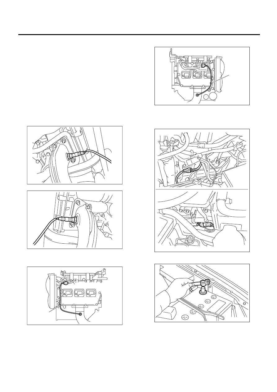
B: INSTALLATION
1) Before installing front oxygen (A/F) sensor, ap-
ply anti-seize compound only to threaded portion of
front oxygen (A/F) sensor to make the next removal
easier.
Anti-seize compound:
SS-30 by JET LUBE
CAUTION:
Never apply anti-seize compound to protector
of front oxygen (A/F) sensor.
2) Install front oxygen (A/F) sensor.
Tightening torque:
21 N·m (2.1 kgf-m, 15.2 ft-lb)
3) Secure harness to clip (A).
• LH side
• RH side
4) Install under cover.
5) Lower the vehicle.
6) Connect connector of front oxygen (A/F) sensor.
7) Connect battery ground cable.
FU-00589
FU-00590
FU-00587
( A )
FU-00588
( A )
EX-00056
LH side
RH side
FU-00009
FU(H6DO)-45
FUEL INJECTION (FUEL SYSTEMS)
REAR OXYGEN SENSOR
16.Rear Oxygen Sensor
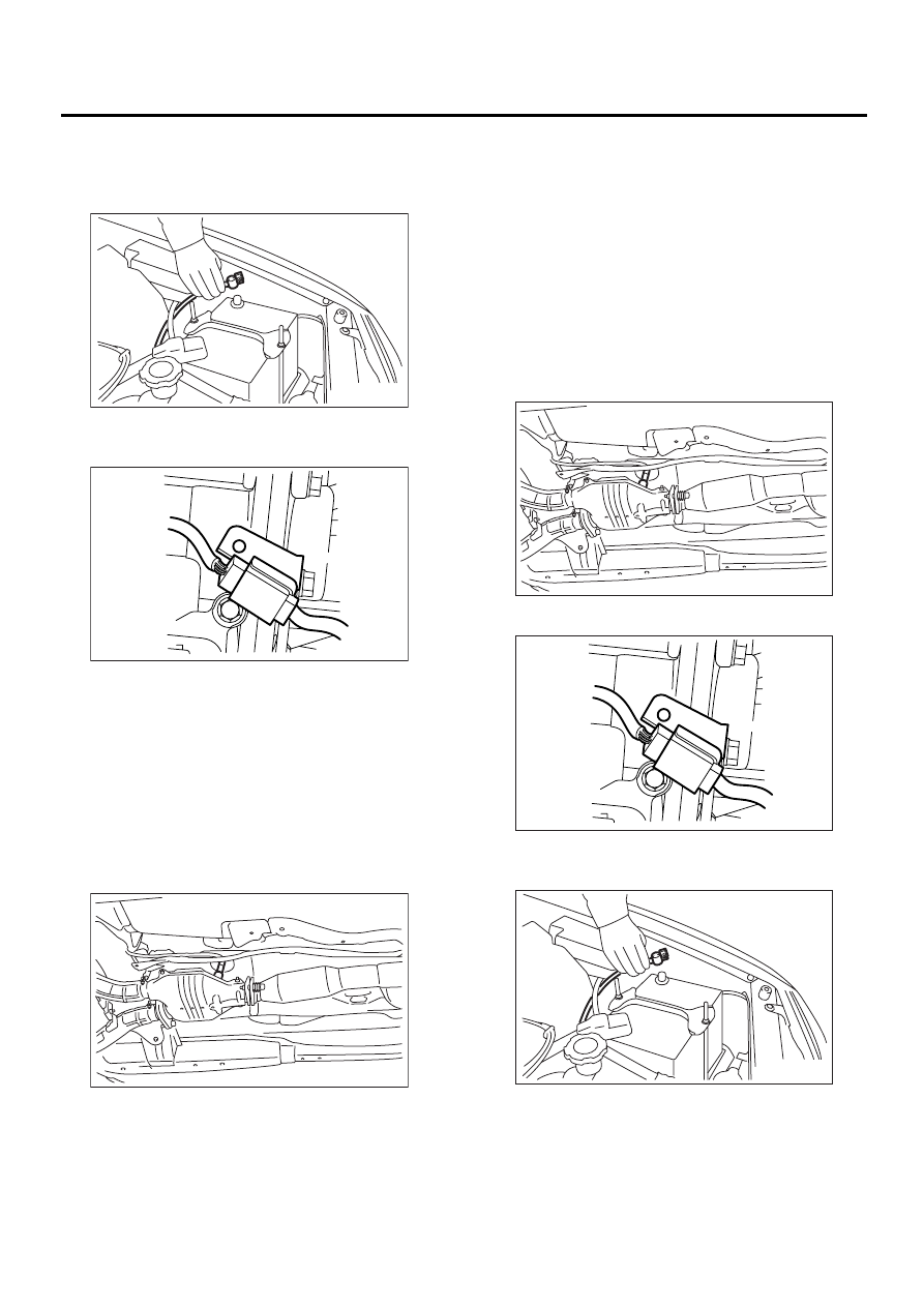
A: REMOVAL
1) Disconnect battery ground cable.
2) Lift-up the vehicle.
3) Disconnect connector from rear oxygen sensor.
4) Apply SUBARU CRC or its equivalent to thread-
ed portion of rear oxygen sensor, and leave it for
one minute or more.
SUBARU CRC (Part No. 004301003)
5) Remove rear oxygen sensor.
CAUTION:
When removing, do not force rear oxygen sen-
sor in an unnatural way especially when ex-
haust pipe is cold, otherwise it will damage
exhaust pipe.
B: INSTALLATION
1) Before installing rear oxygen sensor, apply anti-
seize compound only to threaded portion of rear
oxygen sensor to make the next removal easier.
CAUTION:
Never apply anti-seize compound to protector
of rear oxygen sensor.
Anti-seize compound:
SS-30 by JET LUBE
2) Install rear oxygen sensor.
Tightening torque:
21 N·m (2.1 kgf-m, 15.2 ft-lb)
3) Connect connector to rear oxygen sensor.
4) Lower the vehicle.
5) Connect battery ground cable.
FU-00535
EX-00058
FU-00591
FU-00591
EX-00058
FU-00535
FU(H6DO)-46
FUEL INJECTION (FUEL SYSTEMS)
ENGINE CONTROL MODULE
17.Engine Control Module
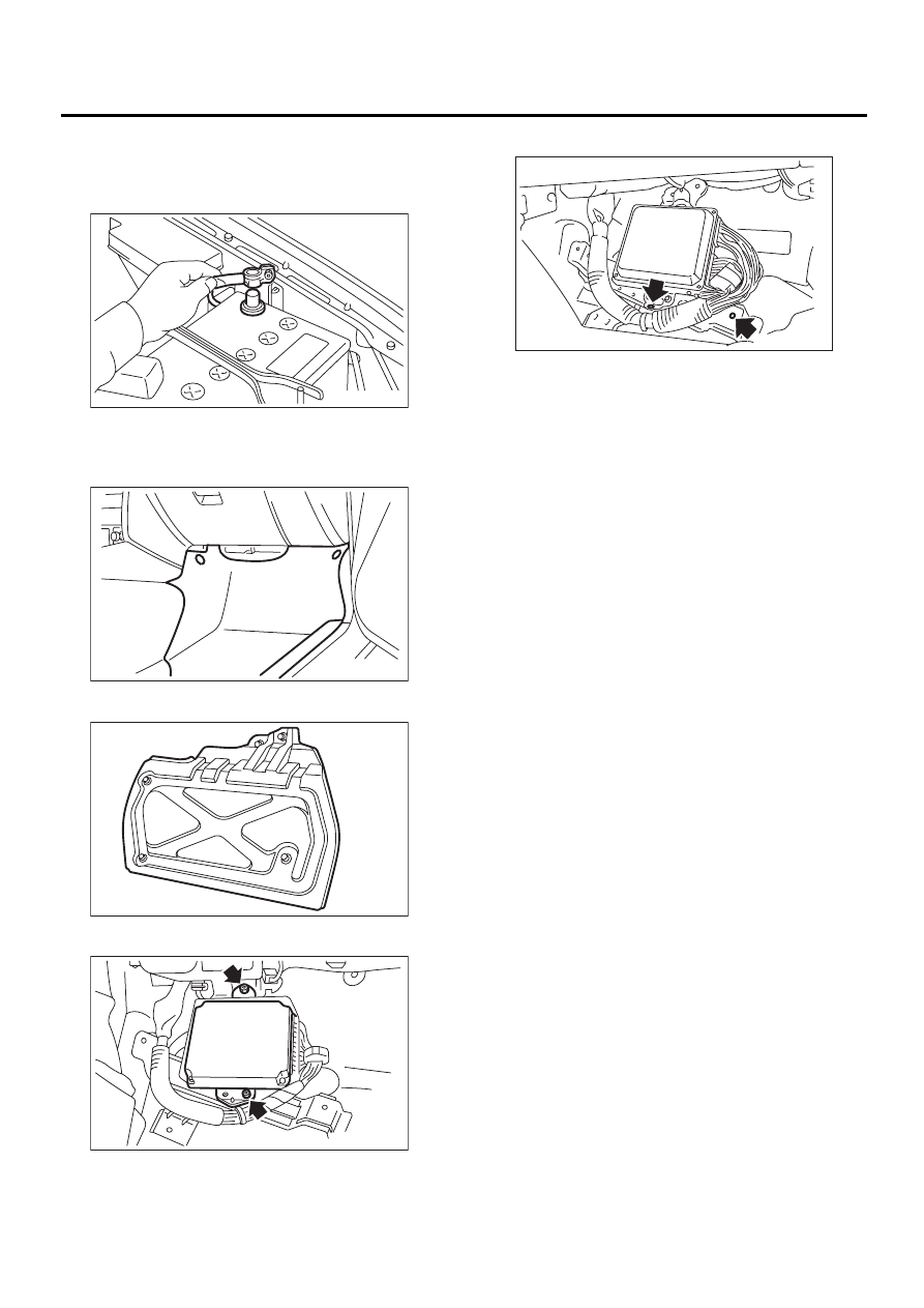
A: REMOVAL
1) Disconnect battery ground cable.
2) Remove lower inner trim of passenger side.
<Ref. to EI-39, REMOVAL, Lower Inner Trim.>
3) Detach floor mat of front passenger seat.
4) Remove protect cover.
5) Remove nuts which hold ECM to bracket.
6) Remove clip from bracket.
7) Disconnect ECM connectors and take out ECM.
B: INSTALLATION
Install in the reverse order of removal.
CAUTION:
When replacing ECM, be careful not to use the
wrong spec. ECM to avoid any damage to the
fuel injection system.
FU-00009
FU-00514
FU-00593
FU-00594
FU-00595
FU(H6DO)-47
FUEL INJECTION (FUEL SYSTEMS)
MAIN RELAY
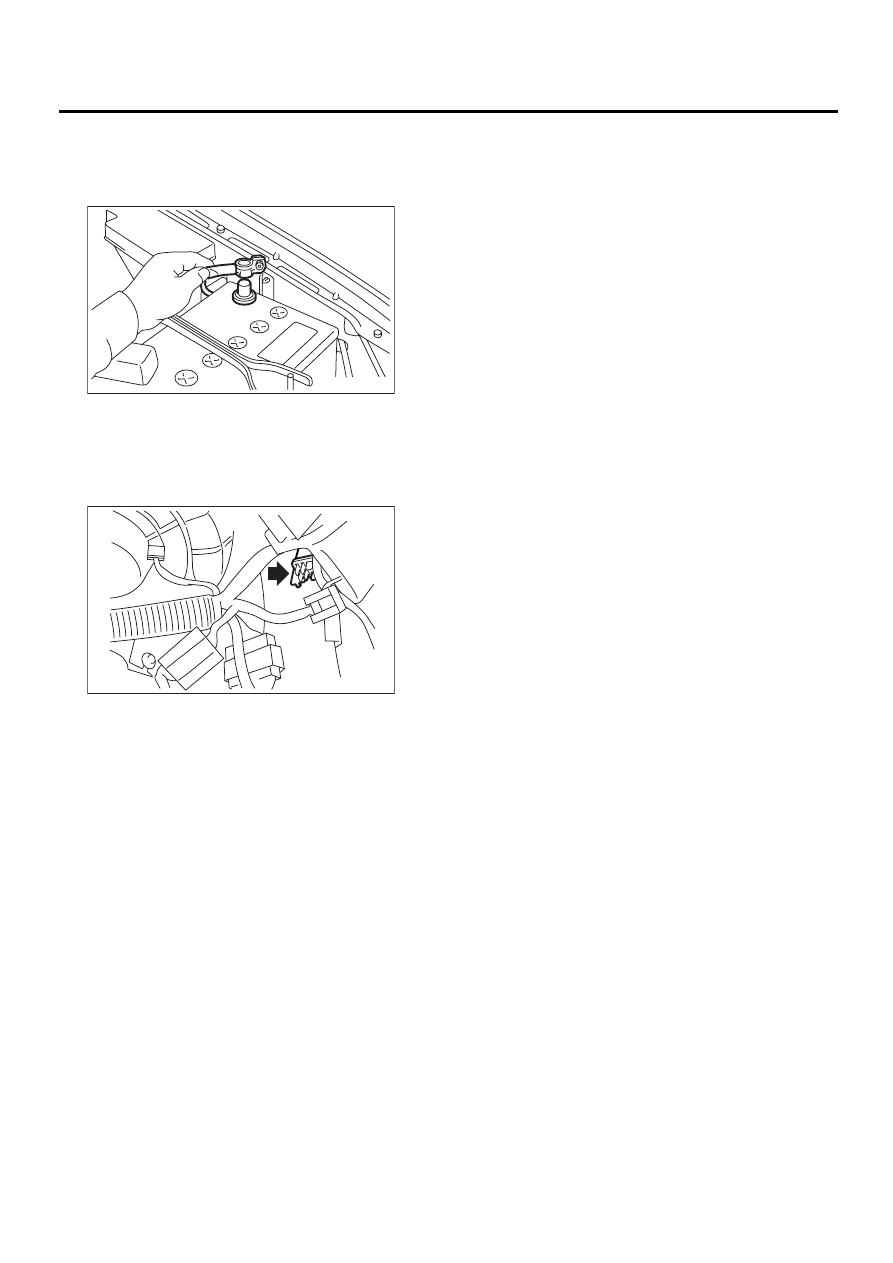
18.Main Relay
A: REMOVAL
1) Disconnect battery ground cable.
2) Remove lower inner trim of passenger side.
<Ref. to EI-39, REMOVAL, Lower Inner Trim.>
3) Disconnect connectors from main relay.
4) Remove bolt which holds main relay bracket on
body.
B: INSTALLATION
Install in the reverse order of removal.
FU-00009
FU-00441
Нет комментариевНе стесняйтесь поделиться с нами вашим ценным мнением.
Текст