Subaru Legacy III (2000-2003 year). Service manual — part 878
AC-48
HVAC SYSTEM (AUTO A/C) (DIAGNOSTICS)
DIAGNOSTICS FOR A/C SYSTEM FAILURE (RHD MODEL)
12
CHECK GROUND CIRCUIT OF SUB FAN
MOTOR.
1) Turn ignition switch to OFF.
2) Measure resistance between sub fan motor
connector and chassis ground.
Connector & terminal
4 CYLINDER MODEL
(F16) No. 1 — Chassis ground:
6 CYLINDER MODEL
(F16) No. 4 — Chassis ground:
Is the measured value less than the speci-
fied value?
1
Ω
Repair harness
between sub fan
motor connector
and chassis
ground.
13
CHECK POOR CONTACT.
Check poor contact in sub fan motor connec-
tor.
Is there poor contact in connector?
There is no poor contact in
connector.
Repair poor con-
tact in sub fan
motor connector.
14
CHECK SUB FAN MOTOR.
4 CYLINDER MODEL
Connect battery positive (+) terminal to termi-
nal No. 2, and negative (
−
) terminal to terminal
No. 1 of sub fan motor connector.
6 CYLINDER MODEL
Connect battery positive (+) terminal to termi-
nal No. 1, 2, 3, and negative (
−
) terminal to ter-
minal No. 4 of sub fan motor connector.
Does the sub fan motor rotate?
Sub fan motor rotates.
Replace sub fan
motor with a new
one.
15
CHECK EACH SENSOR AND POTENTIOME-
TER.
Check the sensors and potentiometer for
proper operation using the self-diagnostic
function. <Ref. to AC-18, OPERATION, Self-
Diagnosis Procedure (RHD Model).>
Is the operation of each sensor and potentiom-
eter normal?
Operation of each sensor and
potentiometer is OK.
Replace sensor
and/or potentiome-
ter.
16
CHECK CONNECTION OF ASPIRATOR
DUCT.
Make sure that the connection of aspirator duct
is correct.
Is the connection of duct correct?
Connection is OK.
Repair aspirator
duct connection.
17
CHECK EACH ACTUATOR.
Check the actuators for proper operation using
the self-diagnostic function. <Ref. to AC-18,
OPERATION, Self-Diagnosis Procedure (RHD
Model).>
Is the operation of each actuator normal?
Operation of each actuator is
OK.
Replace actuator.
18
CHECK POOR CONTACT.
Check poor contact in A/C control module con-
nector.
Is there poor contact in connector?
There is no poor contact.
Replace A/C con-
trol module.
Repair connector.
Step
Value
Yes
No
AC-49
HVAC SYSTEM (AUTO A/C) (DIAGNOSTICS)
LIST OF DIAGNOSTIC TROUBLE CODE (DTC)
9. List of Diagnostic Trouble Code (DTC)
A: LIST (LHD MODEL)
1. DTC FOR SENSOR AND POTENTIOMETER
2. DTC FOR MODE DOOR POSITION SWITCH
B: LIST (RHD MODEL)
1. DTC FOR SENSOR AND POTENTIOMETER
DTC
Trouble Unit
Contents
20
No Trouble
—
21
Ambient sensor
Open
–21
Short
22
In-vehicle sensor
Open
–22
Short
24
Evaporator sensor
Open
–24
Short
25
Sunload sensor
Open
–25
Short
26
Mode door actuator
Open
–26
Short
DTC
30
31
32
33
34
35
Faulty Door
No Trouble
VENT
B/L
HEAT
D/H
DEF
DTC
Trouble Unit
Contents
20
No Trouble
—
21
In-vehicle sensor
Open
–21
Short
22
Ambient sensor
Open
–22
Short
23
Evaporator sensor
Open
–23
Short
25
Sunload sensor
Open
–25
Short
26
Air mix door actuator
FULL COOL
27
FULL HOT
28
Mode door actuator
FULL VENT
29
FULL DEF
AC-50
HVAC SYSTEM (AUTO A/C) (DIAGNOSTICS)
DIAGNOSTIC PROCEDURE WITH DIAGNOSTIC TROUBLE CODE (DTC) (LHD
MODEL)
10.Diagnostic Procedure with Diagnostic Trouble Code (DTC) (LHD
Model)
A: DTC 21 OR –21 (AMBIENT SENSOR)
TROUBLE SYMPTOM:
Fan speed, outlets and inlets are not switched when AUTO or ECON switch is ON.
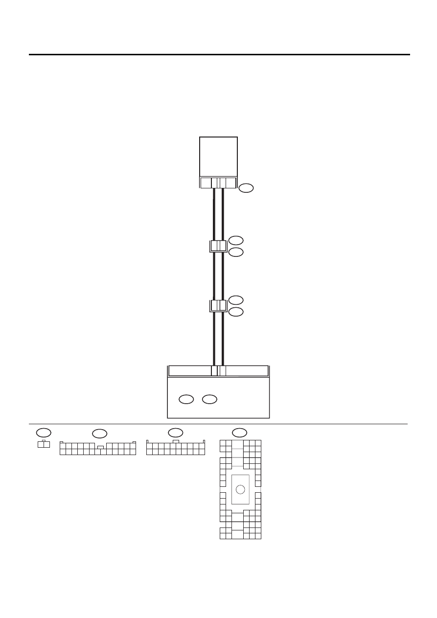
WIRING DIAGRAM:
AC-00371
B17
B6
F78
F2
B100
B36
i1
2
1
AMBIENT
SENSOR
9
8
E6
D6
F78
1 2
i49
B:
1 2 3 4 5 6 7 8 9 10
11 12 13 14 15 16 17 18 19 20
B36
B4 B5 B6
A4 A5 A6
C5 C6
F6
D4 D5 D6
F1
H1
C4
G6
G1
C2
K1
M1 M2
K6
L1
D1 D2
A1 A2
B1 B2
I6
J6
L2
I1
J1
H6
M4 M5 M6
L4 L5 L6
N5 N6
O4 O5 O6
N4
P4 P5
N2
O1 O2
P1 P2
N3
O3
P3
P6
A3
B3
C3
E4 E5 E6
E1 E2
i49
B:
i48
A:
AUTO A/C
CONTROL MODULE
F2
1
12
9
8
7
6
17
5
4
3
2
14
13
15 16
18
21
20
19
22 23 24
11
10

AC-51
HVAC SYSTEM (AUTO A/C) (DIAGNOSTICS)
DIAGNOSTIC PROCEDURE WITH DIAGNOSTIC TROUBLE CODE (DTC) (LHD
MODEL)
Step
Value
Yes
No
1
CHECK AMBIENT SENSOR.
1) Turn ignition switch to OFF.
2) Disconnect connector from ambient sensor.
3) Measure resistance between connector ter-
minals of ambient sensor.
Terminals
No. 1 — No. 2:
Is the measured value the same as speci-
fied value?
Approx. 2.2 k
Ω
: 25
°
C (77
°
F)
Replace ambient
sensor.
2
CHECK INPUT SIGNALS FOR AMBIENT
SENSOR.
1) Turn ignition ON.
2) Measure voltage between ambient sensor
harness connector terminals.
Connector & terminal
(F78) No. 1 (+) — No. 2 (
−−−−
):
Is the measured value the same as speci-
fied value?
Approx. 4.5 V
3
CHECK OUTPUT SIGNALS FROM A/C CON-
TROL MODULE.
1) Turn ignition switch to OFF.
2) Pull out A/C control panel.
3) Disconnect connector from ambient sensor.
4) Turn ignition switch to ON.
5) Measure voltage between connector termi-
nals of A/C control module.
Connector & terminal
(i49) No. 6 (+)— No. 17 (
−−−−
):
Is the measured value the same as speci-
fied value?
Approx. 4.5 V
4
CHECK HARNESS CONNECTOR BETWEEN
A/C CONTROL MODULE AND AMBIENT
SENSOR.
1) Turn ignition switch to OFF.
2) Disconnect connectors from A/C control
module.
3) Measure resistance of harness between A/
C control module and ambient sensor.
Connector & terminal
(F78) No. 1 — (i49) No. 6:
Is the measured value less than the speci-
fied value?
1
Ω
Repair harness
between A/C con-
trol module and
ambient sensor.
5
CHECK HARNESS CONNECTOR BETWEEN
A/C CONTROL MODULE AND AMBIENT
SENSOR.
Measure resistance of harness between A/C
control module and ambient sensor.
Connector & terminal
(F78) No. 2 — (i49) No. 17:
Is the measured value less than the specified
value?
1
Ω
Repair harness
between A/C con-
trol module and
ambient sensor.
6
CHECK POOR CONTACT.
Check poor contact in A/C control module con-
nector.
Is there poor contact in connector?
There is no poor contact.
Replace A/C con-
trol module.
Repair connector.
Нет комментариевНе стесняйтесь поделиться с нами вашим ценным мнением.
Текст