Subaru Legacy III (2000-2003 year). Service manual — part 879
AC-52
HVAC SYSTEM (AUTO A/C) (DIAGNOSTICS)
DIAGNOSTIC PROCEDURE WITH DIAGNOSTIC TROUBLE CODE (DTC) (LHD
MODEL)
B: DTC 22 OR –22 (IN-VEHICLE SENSOR)
TROUBLE SYMPTOM:
When turning AUTO switch to ON, blower fan speed, outlet port and inlet port is not changed.
If DTC 22 or
−
22 appears on the display, replace the A/C control module. The in-vehicle sensor is built into
the A/C control module and cannot be replaced as a single unit.
AC-53
HVAC SYSTEM (AUTO A/C) (DIAGNOSTICS)
DIAGNOSTIC PROCEDURE WITH DIAGNOSTIC TROUBLE CODE (DTC) (LHD
MODEL)
MEMO:
AC-54
HVAC SYSTEM (AUTO A/C) (DIAGNOSTICS)
DIAGNOSTIC PROCEDURE WITH DIAGNOSTIC TROUBLE CODE (DTC) (LHD
MODEL)
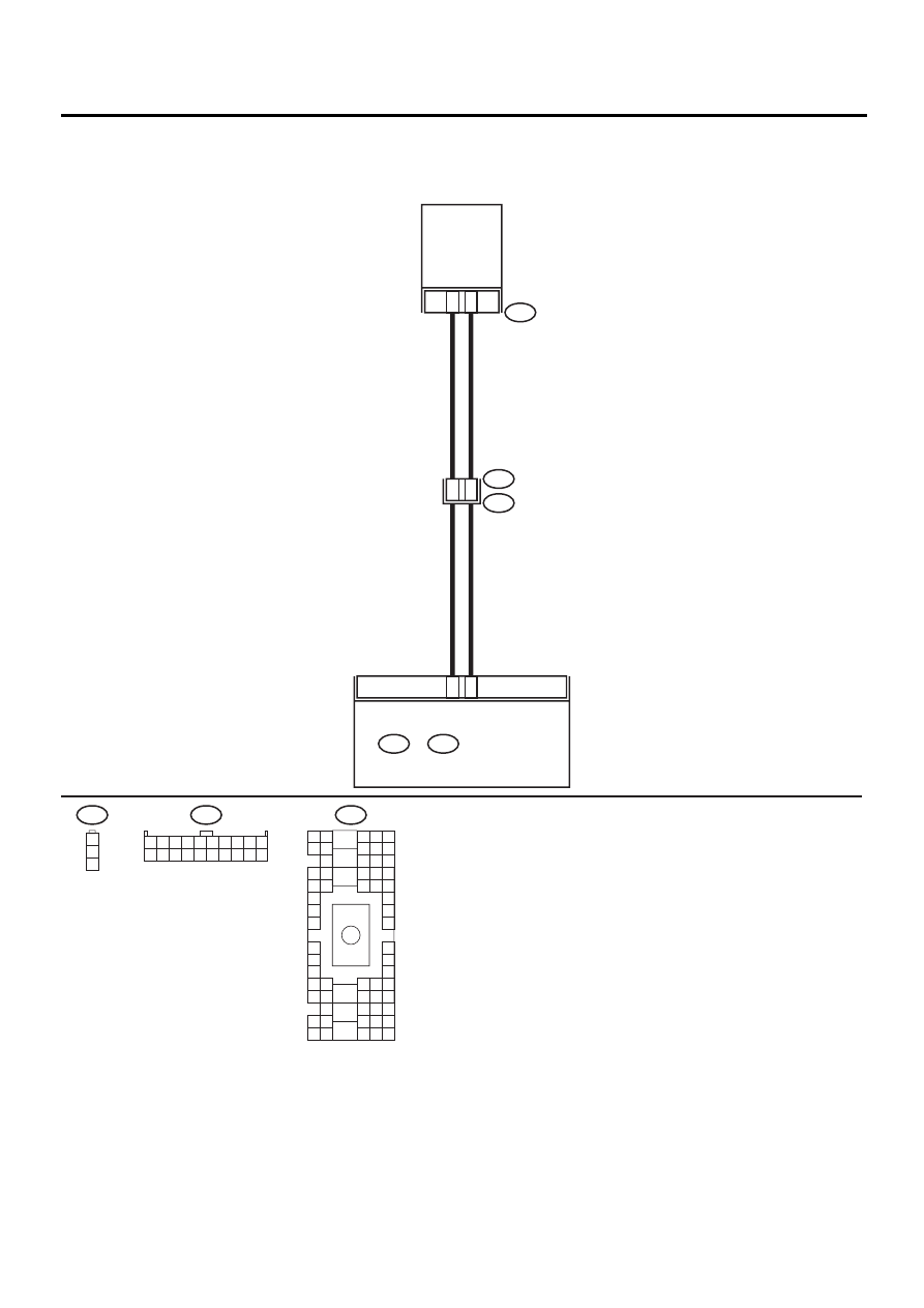
C: DTC 24 OR –24 (EVAPORATOR SENSOR)
WIRING DIAGRAM:
AC-00323
B17
B7
B88
B36
i1
3
1
EVAPORATION
THRMO
SWITCH
J6
i49
B:
1 2 3 4 5 6 7 8 9 10
11 12 13 14 15 16 17 18 19 20
B36
B4 B5 B6
A4 A5 A6
C5 C6
F6
D4 D5 D6
F1
H1
C4
G6
G1
C2
K1
M1 M2
K6
L1
D1 D2
A1 A2
B1 B2
I6
J6
L2
I1
J1
H6
M4 M5 M6
L4 L5 L6
N5 N6
O4 O5 O6
N4
P4 P5
N2
O1 O2
P1 P2
N3
O3
P3
P6
A3
B3
C3
E4 E5 E6
E1 E2
E6
B88
1
2
3
i49
B:
i48
A:
AUTO A/C
CONTROL MODULE

AC-55
HVAC SYSTEM (AUTO A/C) (DIAGNOSTICS)
DIAGNOSTIC PROCEDURE WITH DIAGNOSTIC TROUBLE CODE (DTC) (LHD
MODEL)
Step
Value
Yes
No
1
CHECK EVAPORATOR SENSOR.
1) Turn ignition switch to OFF.
2) Remove glove box.
3) Disconnect connector from evaporator sen-
sor.
4) Measure resistance between connector ter-
minals of evaporator sensor.
Terminals
No. 1 — No. 3:
Is the measured value within the specified
range?
Approx. 1.8 to 2.0 k
Ω
: 20
°
C
(68
°
F)
Replace evapora-
tor sensor.
2
CHECK INPUT SIGNALS FOR EVAPORA-
TOR SENSOR.
1) Turn ignition switch to ON.
2) Measure voltage between evaporator sen-
sor harness connector terminal and chassis
ground.
Connector & terminal
(B88) No. 1 (+) — Chassis ground (
−−−−
):
Is the measured value the same as speci-
fied value?
Approx. 4.5 V
3
CHECK OUTPUT SIGNALS FROM A/C CON-
TROL MODULE.
1) Turn ignition switch to OFF.
2) Pull out A/C control module.
3) Turn ignition switch to ON.
4) Measure voltage between A/C control mod-
ule connector terminals.
Connector & terminal
(i49) No. 7 (+) — No. 17 (
−−−−
):
Is the measured value the same as speci-
fied value?
Approx. 4.5 V
4
CHECK HARNESS CONNECTOR BETWEEN
A/C CONTROL MODULE AND EVAPORA-
TOR SENSOR.
1) Turn ignition switch to OFF.
2) Disconnect connectors from A/C control
module.
3) Measure resistance of harness between A/
C control module and evaporator sensor.
Connector & terminal
(B88) No. 1 — (i49) No. 7:
Is the measured value less than the speci-
fied value?
1
Ω
Repair harness
between A/C con-
trol module and
evaporator sensor.
5
CHECK HARNESS CONNECTOR BETWEEN
A/C CONTROL MODULE AND EVAPORA-
TOR SENSOR.
Measure resistance of harness between A/C
control module and evaporator sensor.
Connector & terminal
(B88) No. 3 — (i49) No. 17:
Is the measured value less than the specified
value?
1
Ω
Repair harness
between A/C con-
trol module and
evaporator sensor.
6
CHECK POOR CONTACT.
Check poor contact in A/C control module con-
nector.
Is there poor contact in connector?
There is no poor contact.
Replace A/C con-
trol module.
Repair connector.
Нет комментариевНе стесняйтесь поделиться с нами вашим ценным мнением.
Текст