Subaru Legacy III (2000-2003 year). Service manual — part 876
AC-40
HVAC SYSTEM (AUTO A/C) (DIAGNOSTICS)
DIAGNOSTICS FOR A/C SYSTEM FAILURE (RHD MODEL)
7
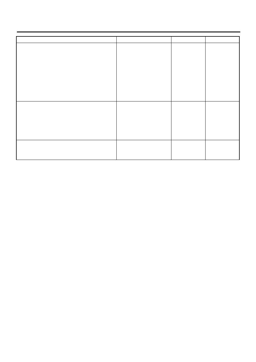
CHECK HARNESS BETWEEN BLOWER
FAN MOTOR RELAY AND A/C CONTROL
MODULE.
1) Disconnect connector from A/C control
module.
2) Measure resistance between blower fan
motor relay and A/C control module har-
ness connector.
Connector & terminal
(B50) No. 3 — (i49) No. 3:
Is the measured value less than the speci-
fied value?
1
Ω
Repair harness
between blower
fan motor relay
and A/C control
module.
8
CHECK UNDER AUTO MODE.
1) Connect all of removed relays and discon-
nected connectors.
2) Start the engine and turn the A/C switch to
ON.
3) Select AUTO mode.
4) Check, if blower fan speed changes.
Does change the blower fan speed?
Blower fan speed changes.
Blower fan is OK.
9
CHECK FOR POOR CONTACT.
Check, if there is poor contact in A/C control
module connector.
Is there poor contact in the connector?
There is no poor contact.
Replace A/C con-
trol module.
Repair poor con-
tact in connector.
Step
Value
Yes
No
AC-41
HVAC SYSTEM (AUTO A/C) (DIAGNOSTICS)
DIAGNOSTICS FOR A/C SYSTEM FAILURE (RHD MODEL)
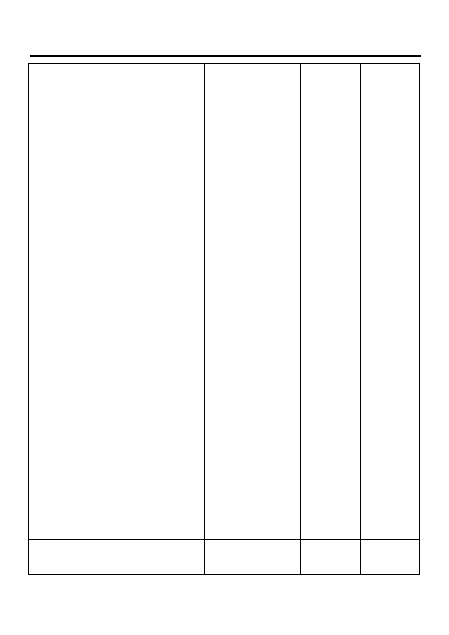
D: FRESH/RECIRC DOES NOT CHANGE
TROUBLE SYMPTOM:
FRESH/RECIRC mode door does not change.

AC-42
HVAC SYSTEM (AUTO A/C) (DIAGNOSTICS)
DIAGNOSTICS FOR A/C SYSTEM FAILURE (RHD MODEL)
WIRING DIAGRAM:
Step
Value
Yes
No
1
CHECK SWITCH OPERATION.
Make sure that the mode selection on display
is changed when pushing the FRESH/RECIRC
switch.
Does the mode selection change?
Mode selection changes.
AC-00368
BATTERY
NO. 17
SBF-1
SBF-4
IGNITION
SWITCH
B12
B2
i48
AUTO A/C
CONTROL
MODULE
A:
i49
B:
i52
C
7
3
1
INTAKE DOOR
ACTUATOR
BLOWER MODULE
1
5
8
C
1 2 3 4 5 6 7
i52
1 2
3 4
5 6
7
8 9
10 11 12 13 14
1 2 3 4 5 6 7 8 9 10
11 12 13 14 15 16 17 18 19 20
B:
i49
AC-43
HVAC SYSTEM (AUTO A/C) (DIAGNOSTICS)
DIAGNOSTICS FOR A/C SYSTEM FAILURE (RHD MODEL)
2
CHECK FUSE.
1) Turn ignition switch to OFF.
2) Remove No. 17 fuse in fuse & relay box.
3) Check condition of fuse.
Is the fuse blown-out?
Fuse is not blown.
Replace fuse.
3
CHECK POWER SUPPLY VOLTAGE TO
BLOWER MODULE.
1) Remove glove box.
2) Turn ignition switch to ON.
3) Measure voltage between blower module
and chassis ground.
Connector & terminal
(i52) No. 1 (+) — Chassis ground (
−−−−
):
Does the measured value exceed the spec-
ified value?
10 V
Repair harness for
power supply line.
4
CHECK SIGNAL VOLTAGE.
1) Change display to RECIRC by pushing
FRESH/RECIRC switch.
2) Measure voltage between A/C control mod-
ule and chassis ground.
Connector & terminal
(i49) No. 12 (+) — Chassis ground (
−−−−
):
Is the measured value less than the speci-
fied value?
1 V
Repair harness for
power supply line.
5
CHECK SIGNAL VOLTAGE.
1) Change display to FRESH by pushing
FRESH/RECIRC switch.
2) Measure voltage between A/C control mod-
ule and chassis ground.
Connector & terminal
(i49) No. 2 (+) — Chassis ground (
−−−−
):
Is the measured value less than the speci-
fied value?
1 V
Repair harness for
power supply line.
6
CHECK HARNESS CONNECTOR BETWEEN
A/C CONTROL MODULE AND BLOWER
MODULE.
1) Turn ignition switch to OFF.
2) Disconnect connector from A/C control
module and blower module.
3) Measure resistance of harness between A/
C control module and blower module.
Connector & terminal
(i49) No. 12 — (i52) No. 8:
Is the measured value less than the speci-
fied value?
1
Ω
Repair harness
between A/C con-
trol module and
blower module.
7
CHECK HARNESS CONNECTOR BETWEEN
A/C CONTROL MODULE AND BLOWER
MODULE.
Measure resistance of harness between A/C
control module and blower module.
Connector & terminal
(i49) No. 2 — (i52) No. 5:
Is the measured value less than the specified
value?
1
Ω
Repair harness
between A/C con-
trol module and
blower module.
8
CHECK POOR CONTACT.
Check poor contact in A/C control module con-
nector.
Is there poor contact in connector?
There is no poor contact.
Replace A/C con-
trol module.
Repair connector.
Step
Value
Yes
No
Нет комментариевНе стесняйтесь поделиться с нами вашим ценным мнением.
Текст