Subaru Legacy III (2000-2003 year). Service manual — part 319

EN(H6DO)-78
ENGINE (DIAGNOSTICS)
DIAGNOSTICS FOR ENGINE STARTING FAILURE
6
CHECK INPUT VOLTAGE OF MAIN RELAY.
Check voltage between main relay connector
and chassis ground.
Connector & terminal
(B47) No. 2 (+) — Chassis ground (–):
Does the measured value exceed the specified
value?
10 V
Repair open circuit
in harness
between ECM
connector and
main relay con-
nector.
7
CHECK GROUND CIRCUIT OF MAIN RE-
LAY.
1) Turn ignition switch to OFF.
2) Measure resistance between main relay
connector and chassis ground.
Connector & terminal
(B47) No. 1 — Chassis ground:
Is the measured value less than the speci-
fied value?
5
Ω
Repair open circuit
between main
relay and chassis
ground.
8
CHECK INPUT VOLTAGE OF MAIN RELAY.
Measure voltage between main relay connec-
tor and chassis ground.
Connector & terminal
(B47) No. 5 (+) — Chassis ground (
−−−−
):
(B47) No. 6 (+) — Chassis ground (
−−−−
):
Does the measured value exceed the specified
value?
10 V
Repair open or
ground short cir-
cuit in harness of
power supply cir-
cuit.
9
CHECK INPUT VOLTAGE OF ECM.
1) Connect main relay connector.
2) Turn ignition switch to ON.
3) Measure voltage between ECM connector
and chassis ground.
Connector & terminal
(B137) No. 2 (+) — Chassis ground (–):
(B137) No. 3 (+) — Chassis ground (–):
Does the measured value exceed the spec-
ified value?
10 V
Check ignition
control system.
<Ref. to
EN(H6DO)-80,
IGNITION CON-
TROL SYSTEM,
Diagnostics for
Engine Starting
Failure.>
Repair open or
ground short cir-
cuit in harness
between ECM
connector and
main relay con-
nector.
Step
Value
Yes
No
EN(H6DO)-79
ENGINE (DIAGNOSTICS)
DIAGNOSTICS FOR ENGINE STARTING FAILURE
MEMO:
EN(H6DO)-80
ENGINE (DIAGNOSTICS)
DIAGNOSTICS FOR ENGINE STARTING FAILURE
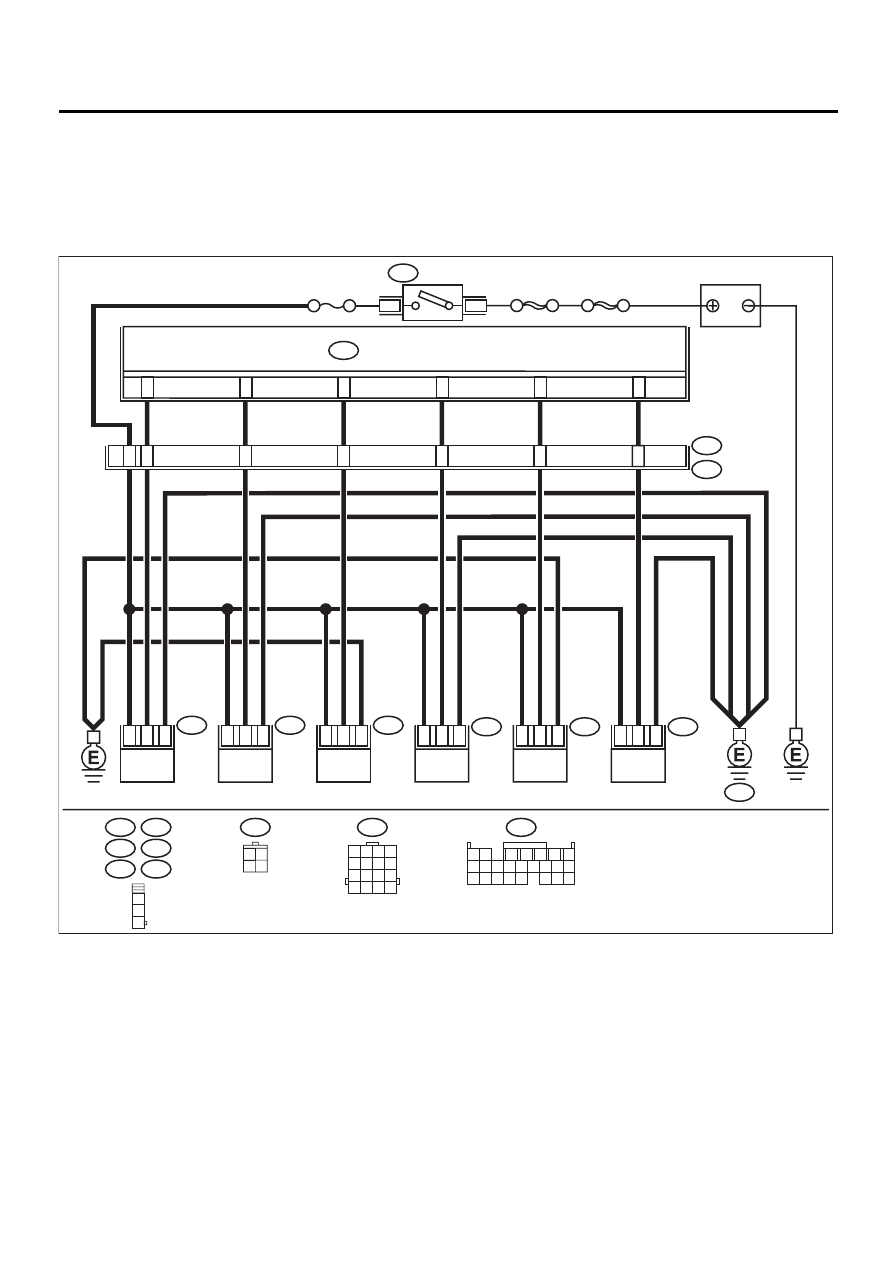
D: IGNITION CONTROL SYSTEM
CAUTION:
After repair or replacement of faulty parts, conduct CLEAR MEMORY MODE <Ref. to EN(H6DO)-54,
OPERATION, Clear Memory Mode.> and INSPECTION MODE <Ref. to EN(H6DO)-47, OPERATION, In-
spection Mode.>.
• WIRING DIAGRAM:
EN-00806
E34
E45
E31
E32
E46
E33
B22
1 2 3 4
5 6 7 8
9 10 11 12
13 14 15 16
1
2
3
B136
1 2
7
8 9
5
6
3
4
10 11 12
19 20 21
13 14 15 16
17 18
22 23 24
B72
3 4
1 2
ENGINE CONTROL MODULE
B136
19
23
24
21
20
22
SBF-4
SBF-1
4
1
B72
IGNITION
SWITCH
NO. 11
E46
E3
B22
E32
6
2
4
1
7
3
2
3
1
2
E34
3
2
E45
3
2
3
5
1
1
1
E31
IGNITION COIL
NO. 1
IGNITION COIL
NO. 2
IGNITION COIL
NO. 3
IGNITION COIL
NO. 4
IGNITION COIL
NO. 5
IGNITION COIL
NO. 6
3
1
2
E33
3
1
2
GE

EN(H6DO)-81
ENGINE (DIAGNOSTICS)
DIAGNOSTICS FOR ENGINE STARTING FAILURE
Step
Value
Yes
No
1
CHECK SPARK PLUG CONDITION.
1) Remove the spark plug. <Ref. to
IG(H6DO)-4, REMOVAL, Spark Plug.>
2) Check the spark plug condition. <Ref. to
IG(H6DO)-5, INSPECTION, Spark Plug.>
Is the spark plug OK?
Spark plug is OK.
Replace the spark
plug.
2
CHECK IGNITION SYSTEM FOR SPARKS.
1) Connect spark plug to ignition coil.
2) Lower fuel pressure.
3) Contact spark plug thread portion with
engine block.
4) While opening throttle valve fully, crank
engine to check that spark occurs at each
cylinder.
Does spark occur at each cylinder?
Spark occurs.
Check fuel pump
system. <Ref. to
EN(H6DO)-84,
FUEL PUMP CIR-
CUIT, Diagnostics
for Engine Start-
ing Failure.>
3
CHECK POWER SUPPLY CIRCUIT FOR IG-
NITION COIL & IGNITOR ASSEMBLY.
1) Turn ignition switch to OFF.
2) Disconnect connector from ignition coil &
ignitor assembly.
3) Turn ignition switch to ON.
4) Measure power supply voltage between
ignition coil & ignitor assembly connector
and engine ground.
Connector & terminal
(E31) No. 3 (+) — Engine ground (
−−−−
):
(E32) No. 3 (+) — Engine ground (
−−−−
):
(E33) No. 3 (+) — Engine ground (
−−−−
):
(E34) No. 3 (+) — Engine ground (
−−−−
):
(E45) No. 3 (+) — Engine ground (
−−−−
):
(E46) No. 3 (+) — Engine ground (
−−−−
):
Does the measured value exceed the spec-
ified value?
10 V
Repair harness
and connector.
NOTE:
In this case, repair
the following:
• Open circuit in
harness between
ignition coil & igni-
tor assembly, and
ignition switch
connector
• Poor contact in
coupling connec-
tors
4
CHECK HARNESS OF IGNITION COIL & IG-
NITOR ASSEMBLY GROUND CIRCUIT.
1) Turn ignition switch to OFF.
2) Measure resistance between ignition coil &
ignitor assembly connector and engine
ground.
Connector & terminal
(E31) No. 2 — Engine ground:
(E32) No. 2 — Engine ground:
(E33) No. 2 — Engine ground:
(E34) No. 2 — Engine ground:
(E45) No. 2 — Engine ground:
(E46) No. 2 — Engine ground:
Is the measured value less than the speci-
fied value?
5
Ω
Repair harness
and connector.
NOTE:
In this case, repair
the following:
• Open circuit in
harness between
ignition coil & igni-
tor assembly con-
nector and engine
grounding terminal
Нет комментариевНе стесняйтесь поделиться с нами вашим ценным мнением.
Текст