Subaru Legacy III (2000-2003 year). Service manual — part 320

EN(H6DO)-82
ENGINE (DIAGNOSTICS)
DIAGNOSTICS FOR ENGINE STARTING FAILURE
5
CHECK HARNESS BETWEEN ECM AND IG-
NITION COIL & IGNITOR ASSEMBLY CON-
NECTOR.
1) Turn ignition switch to OFF.
2) Disconnect connector from ECM.
3) Disconnect connector from ignition coil &
ignitor assembly.
4) Measure resistance of harness between
ECM and ignition coil & ignitor assembly
connector.
Connector & terminal
(B136) No. 24 — (E31) No. 1:
(B136) No. 23 — (E32) No. 1:
(B136) No. 22 — (E33) No. 1:
(B136) No. 21 — (E34) No. 1:
(B136) No. 20 — (E45) No. 1:
(B136) No. 19 — (E46) No. 1:
Is the measured value less than the speci-
fied value?
1
Ω
Repair harness
and connector.
NOTE:
In this case, repair
the following:
• Open circuit in
harness between
ECM and ignition
coil & ignitor
assembly connec-
tor
• Poor contact in
coupling connector
6
CHECK HARNESS BETWEEN ECM AND IG-
NITION COIL & IGNITOR ASSEMBLY CON-
NECTOR.
Measure resistance of harness between ECM
and engine ground.
Connector & terminal:
(B136) No. 24 — Engine ground:
(B136) No. 23 — Engine ground:
(B136) No. 22 — Engine ground:
(B136) No. 21 — Engine ground:
(B136) No. 20 — Engine ground:
(B136) No. 19 — Engine ground:
Does the measured value exceed the specified
value?
1 M
Ω
Repair ground
short circuit in har-
ness between
ECM and ignition
coil & ignitor
assembly connec-
tor.
7
CHECK INPUT SIGNAL FOR IGNITION COIL
& IGNITOR ASSEMBLY.
1) Connect connector to ignition coil & ignitor
assembly.
2) Check if voltage varies synchronously with
engine speed when cranking, while moni-
toring voltage between ignition coil & ignitor
assembly connector and engine ground.
Connector & terminal
(E31) No. 1 (+) — Engine ground (–):
(E32) No. 1 (+) — Engine ground (–):
(E33) No. 1 (+) — Engine ground (–):
(E34) No. 1 (+) — Engine ground (–):
(E45) No. 1 (+) — Engine ground (–):
(E46) No. 1 (+) — Engine ground (–):
Does the measured value exceed the spec-
ified value?
10 V
Replace ignition
coil & ignitor
assembly. <Ref. to
IG(H6DO)-7, Igni-
tion Coil and Igni-
tor Assembly.>
8
CHECK POOR CONTACT.
Check poor contact in ECM connector.
Is there poor contact in ECM connector?
There is poor contact.
Repair poor con-
tact in ECM con-
nector.
Check fuel pump
circuit. <Ref. to
EN(H6DO)-84,
FUEL PUMP CIR-
CUIT, Diagnostics
for Engine Start-
ing Failure.>
Step
Value
Yes
No
EN(H6DO)-83
ENGINE (DIAGNOSTICS)
DIAGNOSTICS FOR ENGINE STARTING FAILURE
MEMO:
EN(H6DO)-84
ENGINE (DIAGNOSTICS)
DIAGNOSTICS FOR ENGINE STARTING FAILURE
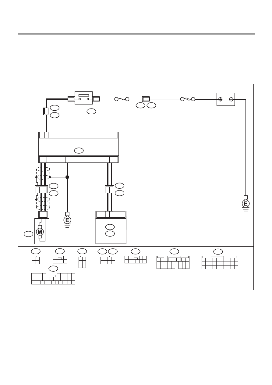
E: FUEL PUMP CIRCUIT
CAUTION:
After repair or replacement of faulty parts, conduct CLEAR MEMORY MODE <Ref. to EN(H6DO)-54,
OPERATION, Clear Memory Mode.> and INSPECTION MODE <Ref. to EN(H6DO)-47, OPERATION, In-
spection Mode.>.
• WIRING DIAGRAM:
• LHD model
EN-01084
10
R57
R58
R15
9
BATTERY
FUEL PUMP
CONTROLLER
FUEL
PUMP
FUEL PUMP
RELAY
SBF-5
F44
B61
B97
B46
R1
6
3
R3
B99
2
4
R122
7
B136
C:
3
5
4
24
25
8
6
5
1 2
7
8 9
5
6
3
4
10 11 12
19 20 21
13 14 15 16
17 18
22 23 24
F44
B97
1 2 3 4
5 6 7 8
C16
ECM
B136
B12
C:
B135
B:
B135
B:
5 6
7 8
2
1
9
4
3
10
24
22
23
25
11 12 13 14 15
26 27 28
16 17 18 19
20 21
2
1
B46
3 4
1 2
R122
1 2
3 4
5 6 7 8 9 10
R57
1
2
3 4 5 6
R58
1 2
3 4
5 6
NO. 13
B99
21
9
32
1 2 3 4
5 6
10 11 12 13 14 15
7
16
23
30
19 20
22
26 27 28 29
8
17
24
31
18
25
EN(H6DO)-85
ENGINE (DIAGNOSTICS)
DIAGNOSTICS FOR ENGINE STARTING FAILURE
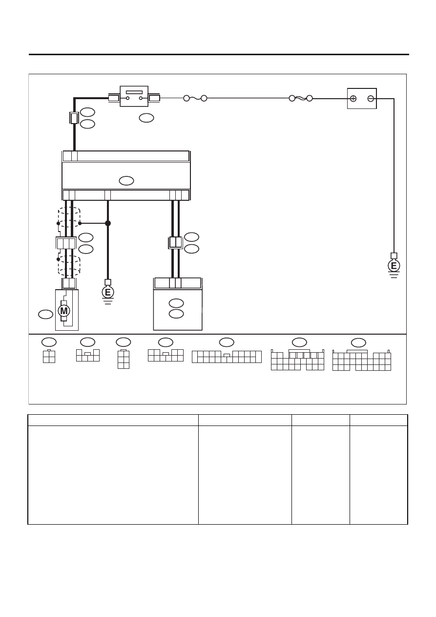
• RHD model
Step
Value
Yes
No
1
CHECK OPERATING SOUND OF FUEL
PUMP.
Make sure that the fuel pump is in operation for
2 seconds when turning ignition switch to ON.
NOTE:
Fuel pump operation check can also be execut-
ed using Subaru Select Monitor.
For the procedure, refer to “Compulsory Valve
Operation Check Mode”. <Ref. to EN(H6DO)-
55, Compulsory Valve Operation Check
Mode.>
Does the fuel pump produce operating sound?
Operating sound produced.
Check fuel injec-
tor circuit. <Ref. to
EN(H6DO)-86,
FUEL INJECTOR
CIRCUIT, Diag-
nostics for Engine
Starting Failure.>
Read the diagnos-
tic Trouble Code
(DTC) and check
related DTC. <Ref.
to EN(H6DO)-89,
List of Diagnostic
Trouble Code
(DTC).>
EN-01085
10
R57
R58
R15
9
BATTERY
FUEL PUMP
CONTROLLER
FUEL
PUMP
FUEL PUMP
RELAY
SBF-5
B99
B46
R3
1
R2
B98
2
4
R122
7
B136
C:
3
5
4
14
16
8
6
5
1 2
7
8 9
5
6
3
4
10 11 12
19 20 21
13 14 15 16
17 18
22 23 24
C16
ECM
B136
B12
C:
B135
B:
B135
B:
5 6
7 8
2
1
9
4
3
10
24
22
23
25
11 12 13 14 15
26 27 28
16 17 18 19
20 21
2
1
B46
3 4
1 2
R122
1 2
3 4
5 6 7 8 9 10
R57
1
2
3 4 5 6
R58
1 2
3 4
5 6
NO. 13
R2
2 3 4 5
6 7 8 9
11 12 13 14
17 18 19 20
10
1
15 16
Нет комментариевНе стесняйтесь поделиться с нами вашим ценным мнением.
Текст