Subaru Legacy III (2000-2003 year). Service manual — part 318

EN(H6DO)-74
ENGINE (DIAGNOSTICS)
DIAGNOSTICS FOR ENGINE STARTING FAILURE
7
CHECK INPUT VOLTAGE OF INHIBITOR
SWITCH.
1) Turn ignition switch to OFF.
2) Disconnect connector from inhibitor switch.
3) Connect connector to ignition switch.
4) Measure input voltage between inhibitor
switch connector terminal and engine
ground while turning ignition switch to ST.
Connector & terminal
(B12) No. 12 (+) — Engine ground (–):
Is the voltage more than 10 V? Go to step 8.
Repair open or
ground short cir-
cuit in harness
between inhibitor
switch and ignition
switch.
8
CHECK INHIBITOR SWITCH CIRCUIT.
1) Turn ignition switch to OFF.
2) Place the selector lever in the “P” or “N”
position.
3) Separate transmission harness connector.
4) Measure resistance between transmission
harness connector terminals.
Connector & terminal
(T3) No. 11 — No. 12:
Is the measured value less than the speci-
fied value?
1
Ω
Repair open or
short circuit in har-
ness between
starter motor and
inhibitor switch.
9
CHECK TRANSMISSION HARNESS.
1) Disconnect connector from inhibitor switch.
2) Measure resistance of harness between
transmission harness and inhibitor switch
connector.
Connector & terminal
(T3) No. 12 — (T7) No. 12:
(T3) No. 11 — (T7) No. 7:
Is the measured value less than the speci-
fied value?
1
Ω
Repair open or
short circuit in har-
ness between
transmission har-
ness and inhibitor
switch connector.
10
CHECK POOR CONTACT.
Check poor contact in inhibitor switch connec-
tor.
Is there poor contact in inhibitor switch connec-
tor?
There is poor contact.
Repair poor con-
tact in inhibitor
switch connector.
Replace inhibitor
switch.
Step
Value
Yes
No
EN(H6DO)-75
ENGINE (DIAGNOSTICS)
DIAGNOSTICS FOR ENGINE STARTING FAILURE
MEMO:
EN(H6DO)-76
ENGINE (DIAGNOSTICS)
DIAGNOSTICS FOR ENGINE STARTING FAILURE
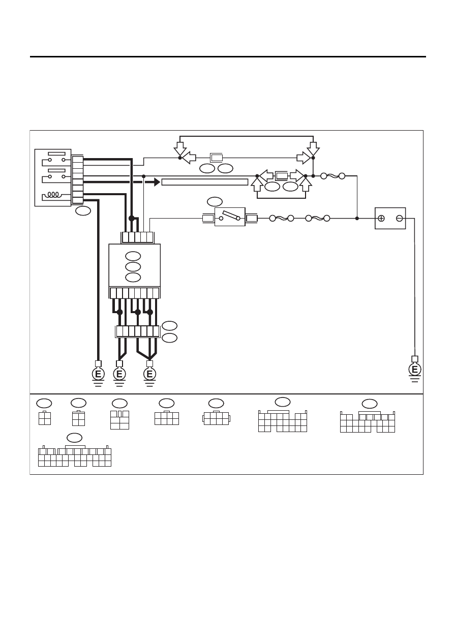
C: CONTROL MODULE POWER SUPPLY AND GROUND LINE
CAUTION:
After repair or replacement of faulty parts, conduct CLEAR MEMORY MODE <Ref. to EN(H6DO)-54,
OPERATION, Clear Memory Mode.> and INSPECTION MODE. <Ref. to EN(H6DO)-47, OPERATION, In-
spection Mode.>
• WIRING DIAGRAM:
EN-01083
D10
A14
D2
A2
D3
E49
B252
D9
C8
D8
D31
D21
5
1
3
B47
BATTERY
MAIN RELAY
1
2
3
5
6
4
F44
B61
SBF-5
6
F46
B108
2
SBF-4
SBF-1
4
1
B72
IGNITION
SWITCH
ECM
B134
A:
B136
C:
B137
D:
A22
7
B137
B136
C:
D:
A: B134
B47
3
4
1
2
5
6
B72
F44
F46
3 4
1 2
B252
C18
C17
TO FRONT OXYGEN (A/F) SENSOR
6
1 2 3 4
5 6 7 8
3 4
1 2
1
2
7
8
9
5
6
3
4
10 11 12
19 20 21
29 30 31
13 14 15 16 17
27 28
18
22 23 24 25 26
1 2
7
8 9
5
6
3
4
10 11 12
19 20 21
13 14 15 16
17 18
22 23 24
1 2 3 4
10 11 12
19 20 21
13
5
6
14 15
7
8 9
16 17
18
22
1 2 3 4
5 6 7 8
LHD
RHD
RHD
RHD
RHD
LHD
LHD
LHD

EN(H6DO)-77
ENGINE (DIAGNOSTICS)
DIAGNOSTICS FOR ENGINE STARTING FAILURE
Step
Value
Yes
No
1
CHECK MAIN RELAY.
1) Turn the ignition switch to OFF.
2) Remove main relay.
3) Connect battery to main relay terminals No.
1 and No. 2.
4) Measure resistance between main relay
terminals.
Terminals
No. 3 — No. 5:
No. 4 — No. 6:
Is the measured value less than the speci-
fied value?
10
Ω
Replace main
relay.
2
CHECK GROUND CIRCUIT OF ECM.
1) Disconnect connector from ECM.
2) Measure resistance of harness between
ECM and chassis ground.
Connector & terminal
(B134) No. 22 — Chassis ground:
(B136) No. 8 — Chassis ground:
(B136) No. 17 — Chassis ground:
(B136) No. 18 — Chassis ground:
(B137) No. 8 — Chassis ground:
(B137) No. 9 — Chassis ground:
(B137) No. 21 — Chassis ground:
(B137) No. 31 — Chassis ground:
Is the measured value less than the speci-
fied value?
5
Ω
Repair open circuit
in harness
between ECM
connector and
engine grounding
terminal.
3
CHECK INPUT VOLTAGE OF ECM.
1) Turn ignition switch to ON.
2) Measure voltage between ECM connector
and chassis ground.
Connector & terminal
(B137) No. 10 (+) — Chassis ground (–):
(B134) No. 14 (+) — Chassis ground (–):
Does the measured value exceed the spec-
ified value?
10 V
Repair open or
ground short cir-
cuit of power sup-
ply circuit.
4
CHECK HARNESS BETWEEN ECM AND
MAIN RELAY CONNECTOR.
1) Turn ignition switch to OFF.
2) Measure resistance between ECM and
chassis ground.
Connector & terminal
(B134) No. 2 — Chassis ground:
Does the measured value exceed the spec-
ified value?
1 M
Ω
Repair ground
short circuit in har-
ness between
ECM connector
and main relay
connector, then
replace ECM.
5
CHECK OUTPUT VOLTAGE FROM ECM.
1) Connect connector to ECM.
2) Turn ignition switch to ON.
3) Measure voltage between ECM connector
and chassis ground.
Connector & terminal
(B134) No. 2 (+) — Chassis ground (–):
Does the measured value exceed the spec-
ified value?
10 V
Replace ECM.
Нет комментариевНе стесняйтесь поделиться с нами вашим ценным мнением.
Текст