Subaru Legacy III (2000-2003 year). Service manual — part 869
AC-12
HVAC SYSTEM (AUTO A/C) (DIAGNOSTICS)
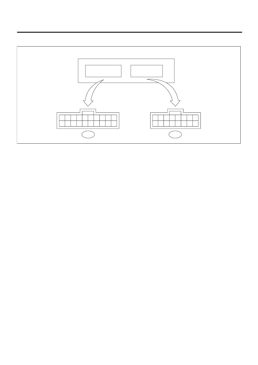
A/C CONTROL MODULE I/O SIGNAL
2. RHD MODEL
(1) A/C control module
(2) To (i49): b
(3) To (i48): a
AC-00316
10
20
9
19
8
18
7
17
6
16
5
15
4
14
3
13
2
12
1
11
8
16
7
15
6
14
5
13
4
12
3
11
2
10
1
9
i49
To
: b
i48
To
: a
A/C control modules

AC-13
HVAC SYSTEM (AUTO A/C) (DIAGNOSTICS)
A/C CONTROL MODULE I/O SIGNAL
B: SCHEMATIC
<Ref. to WI-62, SCHEMATIC, Air Conditioning System.>
Content
Connector &
Terminal No.
Signal (V)
BATT voltage (Memory back-up)
a1—a9
BATT voltage,
13 — 14 (engine running)
IGN power supply
a2—a9
Battery voltage (ignition switch ON),
13 — 14 (engine running)
ACC power supply
(OFF: ignition in START or diag-
nosis system reset)
a3—a9
BATT voltage, 0 (engine cranking), BATT voltage during engine starts
Sensor standard voltage
a5—a9
5 (ignition switch ON)
A/C control module ground circuit
a9—body
0 (ignition switch ON) — circuit constantly grounded
Sensor ground circuit
a10—body
0 (ignition switch ON) — circuit constantly grounded
Ambient sensor
a11—a10
Approx. 3.3 (disconnect connector, and ignition switch ON)
Evaporator sensor
a12—a10
Thermometer
a13—a9
Sunload sensor
a5—a4
Approx. 4.2 (disconnect connector, and ignition switch ON)
Air mix door actuator
b1—b11
BATT voltage (AUTO mode) positive “+” at terminal “b1” and negative “–” at
“b11” [temperature set at 18
°
C (65
°
F)]; negative “–” at terminal “b1” and pos-
itive “+” at “b11” [temperature set at 32
°
C (90
°
F)]
Air mix door actuator P.B.R.
a6—a10
Approx. 0.5 [temperature set at 18
°
C (65
°
F) in AUTO mode]
Approx. 4.5 [temperature set at 32
°
C (90
°
F) in AUTO mode]
Mode door actuator
a8—a16
BATT voltage (ignition switch ON in MANUAL mode); positive “+” at terminal
“a8” and negative “–” at “a8” (VENT); negative “–” at “a16” and positive “+” at
“a16” (DEF)
Mode door actuator P.B.R.
a14—a10
BATT voltage (ignition switch ON in MANUAL mode)
Approx. 4.5 (VENT); approx. 0.5 (DEF)
Intake door FRS actuator voltage
b2—a9
BATT voltage (DEF switch ON)
Intake door CIRC actuator voltage
b12—a9
BATT voltage (CIRC switch ON)
Blower fan relay
b3—a9
BATT voltage (ignition switch ON, blower switch OFF)
Blower fan relay
b5—a9
0 (ignition ON, manual blower HI)
5 (ignition ON, manual blower LO)
Rear defogger relay
b13—a9
0 (ignition switch ON, Rear DEF switch ON)
A/C relay
a7—a9
BATT voltage (ignition and A/C switches ON)
0 (A/C switch OFF)
Illumination control signal
b10—a9
BATT voltage (ignition and lighting switches ON)
AC-14
HVAC SYSTEM (AUTO A/C) (DIAGNOSTICS)
SELF-DIAGNOSIS PROCEDURE (LHD MODEL)
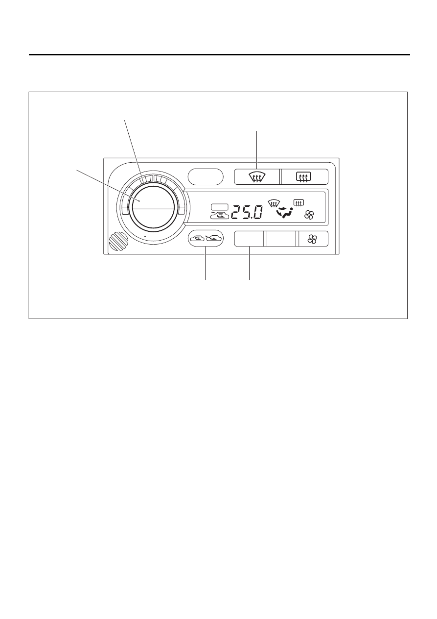
5. Self-Diagnosis Procedure (LHD Model)
A: OPERATION
(1) Temperature control dial
(3) FRESH/RECIRC switch
(5) MODE switch
(2) AUTO switch
(4) DEF switch
AC-00317
OUT.TEMP
OUT.TEMP
BRIGHT
MODE
AUTO
OFF
ECON
A/C
A/C
AUTO
( 5 )
( 3 )
( 2 )
( 4 )
( 1 )

AC-15
HVAC SYSTEM (AUTO A/C) (DIAGNOSTICS)
SELF-DIAGNOSIS PROCEDURE (LHD MODEL)
Step
Value
Yes
No
1
SELECT CONTROL PANEL TO SELF-DIAG-
NOSIS MODE.
1) Turn ignition switch to OFF.
2) While pushing “AUTO” and “FRESH/
RECIRC” switches, start the engine.
Can it be moved to the self-diagnosis
mode?
It can be moved to self-diagno-
sis mode.
2
CHECK INDICATOR.
1) Turn temperature control dial clockwise by
one click.
2) Make sure that all characters illuminate on
the display.
Does each character illuminate?
Each character illuminates.
3
CHECK EACH SENSOR AND EACH POTEN-
TIOMETER.
1) Turn temperature control dial clockwise by
one click.
2) If system has the trouble for each sensor
and/or each potentiometer, DTC is indi-
cated on indicator.
3) If system has no trouble, DTC “20” is indi-
cated on indicator.
NOTE:
When the sunload sensor is checked inside the
passenger compartment or in the shade, DTC
“25” may appear on the indicator. Always check
the sunload sensor in a place where it senses
direct sunlight.
Is the DTC “20” indicated on indicator?
DTC “20” indicated.
Perform diagnosis
procedure accord-
ing to the dis-
played DTC. <Ref.
to AC-49, DTC
FOR SENSOR
AND POTENTI-
OMETER, LIST
(LHD MODEL),
List of Diagnostic
Trouble Code
(DTC).>
4
CHECK DOOR MOTOR POSITION SWITCH.
1) Turn temperature control dial clockwise by
one click.
2) If system has the trouble for each door
position switch, DTC is indicated on indica-
tor.
3) If system has no trouble, DTC “30” is indi-
cated on indicator.
Is the DTC “30” indicated on indicator?
DTC “30” indicated.
Perform diagnosis
procedure for
mode door actua-
tor. <Ref. to AC-
58, DTC 31, 32,
33, 34 OR 35
(MODE DOOR
ACTUATOR),
Diagnostic Proce-
dure with Diagnos-
tic Trouble Code
(DTC) (LHD
Model).>
5
CHECK OPERATION OF EACH ACTUATOR,
BLOWER FAN AND COMPRESSOR
CLUTCH.
1) Turn temperature control dial clockwise by
one click.
2) Select operating mode by pushing every
“DEF” switch.
3) Check the operation for each mode.
•Air inlet:
•Air outlet:
•Air mix door:
•Blower fan:
•A/C compressor:
Does each mode displayed match the oper-
ating mode table? <Ref. to AC-16, OPER-
ATING MODE TABLE, OPERATION, Self-
Diagnosis Procedure (LHD Model).>
Each mode displayed match
the operating mode table.
Нет комментариевНе стесняйтесь поделиться с нами вашим ценным мнением.
Текст