Subaru Legacy III (2000-2003 year). Service manual — part 867

AC-4
HVAC SYSTEM (AUTO A/C) (DIAGNOSTICS)
BASIC DIAGNOSTIC PROCEDURE
6
CHECK A/C SYSTEM RESPONSE.
Change the temperature setting, and check
response of A/C system.
Dose A/C system respond quickly?
A/C system responds quickly.
A/C system is OK. LHD: <Ref. to AC-
24, COMPART-
MENT TEMPERA-
TURE DOES NOT
CHANGE FROM
“SET” TEMPERA-
TURE OR AIR
CONDITIONING
SYSTEM DOES
NOT RESPOND
QUICKLY, Diag-
nostics for A/C
System Failure
(LHD Model).>
RHD: <Ref. to AC-
44, COMPART-
MENT TEMPERA-
TURE DOES NOT
CHANGE FROM
“SET” TEMPERA-
TURE OR AIR
CONDITIONING
SYSTEM DOES
NOT RESPOND
QUICKLY, Diag-
nostics for A/C
System Failure
(RHD Model).>
Step
Value
Yes
No
AC-5
HVAC SYSTEM (AUTO A/C) (DIAGNOSTICS)
GENERAL DESCRIPTION
2. General Description
A: CAUTION
1) Never connect the battery in reverse polarity.
• The auto A/C control module may be destroyed
instantly.
2) Do not disconnect the battery terminals while the
engine is running.
• A large counter electromotive force will be gener-
ated in the alternator, and this voltage may damage
electronic parts such as A/C control module.
3) Before disconnecting the connectors of each
sensor and the A/C control module, be sure to turn
off the ignition switch.
• Otherwise, the Auto A/C control module may be
damaged.
4) Every auto A/C-related part is a precision part.
Do not drop them.
5) Airbag system wiring harness is routed near the
A/C control panel (A/C control module) and junction
box.
CAUTION:
• All airbag system wiring harness and con-
nectors are colored yellow. Do not use electri-
cal test equipment on these circuits.
• Be careful not to damage Airbag system wir-
ing harness when servicing the A/C control
panel (A/C control module) and junction box.
B: INSPECTION
Before performing diagnosis, check the following
items which might affect engine problems.
1. BATTERY
1) Measure battery voltage and specific gravity of
electrolyte.
Standard voltage: 12 V
Specific gravity: Above 1.260
2) Check the condition of the fuses for A/C, heater
and other fuses.
3) Check the condition of the harnesses and har-
ness connectors connection.
2. ASPIRATOR HOSE
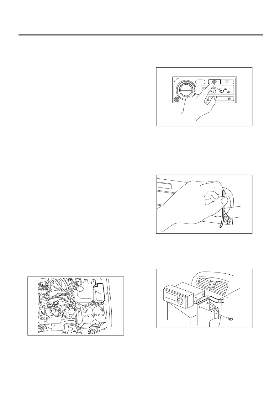
1) Turn ignition switch to ON.
2) Push “DEF” switch and then blower fan switch to
turn the blower fan to maximum speed.
3) Firmly hold a thin thread (b) in front of the in-ve-
hicle sensor suction port (a) for the auto A/C control
unit and check that the thread moves towards the
port indicating that air is being sucked into the port.
NOTE:
• Ensure the thread does not get sucked into the
port.
4) If the thread does not move at all, remove the
auto A/C control unit <Ref. to AC-34, REMOVAL,
Control Unit.> and check for improper connection
of the aspirator hose (a) and auto A/C control unit
and secure as necessary.
(a) Main fuse box
( a )
AC-00309
AC-00310
AUTO
OFF
A/C
OUT.TEMP
AC-00311
( a )
( b )
AC-00312
( a )
AC-6
HVAC SYSTEM (AUTO A/C) (DIAGNOSTICS)
GENERAL DESCRIPTION
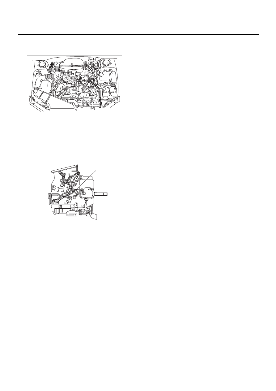
3. REFRIGERANT LINE
Check contact for refrigerant line (A).
4. CONTROL LINKAGE
1) Check state of mode door control rod and link-
age.
2) Check state of air mix door control rod and link-
age.
3) Check state of intake door control rod and link-
age.
(a) Control rod
( A )
AC-00313
AC-00314
( a )
AC-7
HVAC SYSTEM (AUTO A/C) (DIAGNOSTICS)
GENERAL DESCRIPTION
5. CONTROL SWITCHES
Start and warm up engine completely.
1) Inspection using switches.
2) Compressor operation inspection
3) Illumination control inspection
No.
Point to check
Switch operation
Judgement standard
1
OFF switch
OFF switch “ON”
“SET” temperature display go out.
• Air flow
→
OFF
• Outlet
→
HEAT
• Inlet
→
FRESH
• Compressor
→
OFF
2
AUTO switch
A. AUTO switch “ON”
B. Temp. control dial 18
°
C (65
°
F) (Max.
Cold)
a. AUTO switch display illuminates.
b.
• Outlet air
→
Cool
• Air flow
→
HI (AUTO)
• Outlet
→
VENT
• Inlet
→
AUTO
• Compressor
→
AUTO
C. TEMP control dial is gradually set from
18
°
C (65
°
F) to 32
°
C (85
°
F).
c. Air and air outlet mode change as follows:
• Outlet air: cool
→
hot
• Air flow: AUTO
• Outlet: VENT
→
BI-LEVEL
→
HEAT
• Inlet: AUTO
D. Temp. control dial 32
°
C (85
°
F) (Max. Hot)
d. Outlet air
→
Hot
• Air flow
→
HI (AUTO)
• Outlet
→
HEAT
• Inlet
→
FRESH (AUTO)
• Compressor
→
AUTO
3
DEF switch
A. DEF switch “ON”
B. Temp. control dial 18 — 32
°
C (65 — 85
°
F)
a. DEF switch display illuminates.
b.
• Outlet air temperature (AUTO control)
• Air flow (AUTO control)
• Outlet
→
DEF
• Inlet
→
FRESH
• Compressor
→
ON
4
FRESH/RECIRC
switch
FRESH/RECIRC switch “ON”
Changes from RECIRC
→
FRESH, or FRESH
→
RECIRC.
5
MODE switch
MODE switch “ON”
Outlet changes from VENT
→
BI-LEVEL
→
HEAT
→
DEF/HEAT each time MODE switch is pushed.
6
FAN switch
FAN switch “ON”
Fan speed changes from LO
→
M1
→
M2
→
HI each
time FAN switch is pushed.
7
OUT-TEMP
switch
OUT-TEMP switch “ON”
Ambient temperature flashes on “set” temperature dis-
play, and “set” temperature appears.
No.
Point to check
Switch operation
Judgement standard
Remarks
1
Compressor
A. AUTO switch “ON”
B. A/C switch “ON”
C. DEF switch “ON”
a. Compressor ON
b. Compressor ON
c. Compressor ON
Compressor turns OFF several
seconds after AUTO switch is
turned ON.
No.
Point to check
Switch operation
Judgement standard
Remarks
1
Illumination
Lighting switch “ON”
Illumination light illuminates and both switch
light and “set” temperature display dim.
Green lights remain on although
OFF and OUT-TEMP switches
remain ON.
Press OFF switch
longer than 1 second.
Dimming of illumination is canceled.
Нет комментариевНе стесняйтесь поделиться с нами вашим ценным мнением.
Текст