Subaru Legacy III (2000-2003 year). Service manual — part 868
AC-8
HVAC SYSTEM (AUTO A/C) (DIAGNOSTICS)
ELECTRICAL COMPONENTS LOCATION
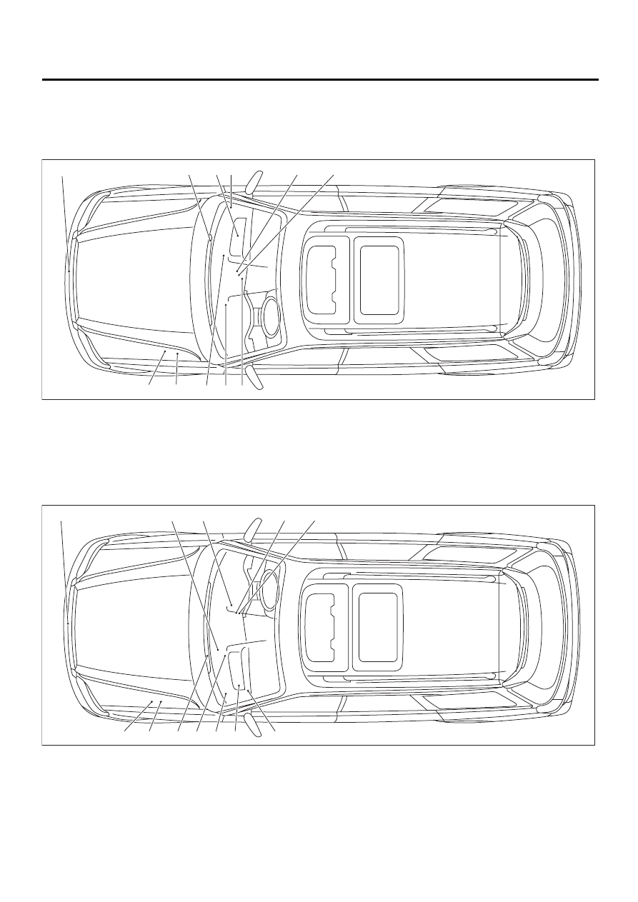
3. Electrical Components Location
A: LOCATION
1. LHD MODEL
2. RHD MODEL
(1) Ambient sensor
(5) Evaporator sensor
(9) A/C relay
(2) Blower motor
(6) Auto A/C control module
(10) A/C fuse
(3) In-vehicle sensor
(7) Air mix door actuator
(11) Mode door actuator
(4) Sunload sensor
(8) Intake door actuator
(1) Ambient sensor
(5) Evaporator sensor
(9) Intake door actuator
(2) Heater module
(6) Blower module
(10) A/C relay
(3) In-vehicle sensor
(7) Auto A/C control module
(11) A/C fuse
(4) Sunload sensor
(8) Air mix door actuator
(12) Mode door actuator
AC-00315
( 7 )
( 5 )
( 9 )
( 3 )
( 6 )
( 8 )
( 2 )
( 4 )
( 1 )
(10)
(11)
AC-00360
( 6 )
( 2 )
( 9 )
( 5 )
( 4 )
( 3 )
( 7 )
( 8 )
( 1 )
(10)
(11)
(12)
AC-9
HVAC SYSTEM (AUTO A/C) (DIAGNOSTICS)
ELECTRICAL COMPONENTS LOCATION
MEMO:
AC-10
HVAC SYSTEM (AUTO A/C) (DIAGNOSTICS)
A/C CONTROL MODULE I/O SIGNAL
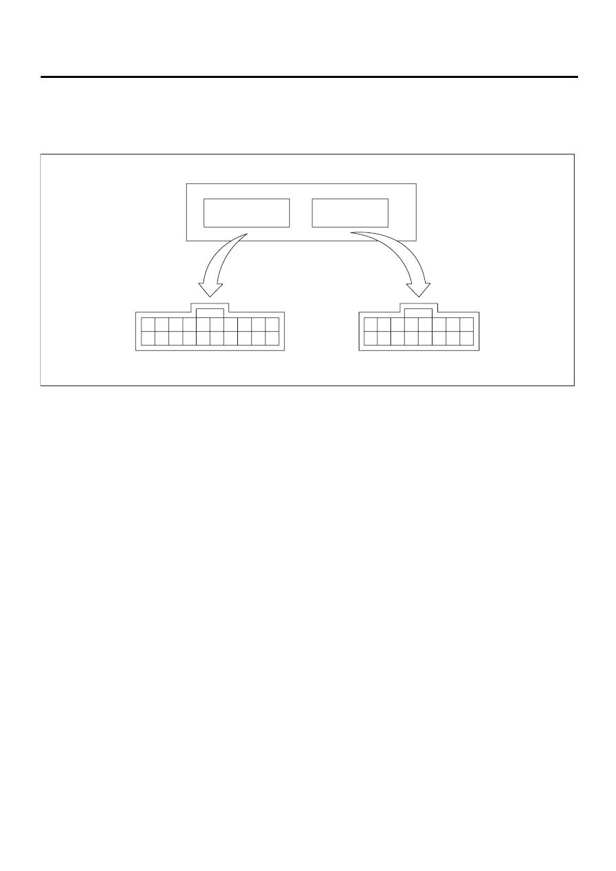
4. A/C Control Module I/O Signal
A: ELECTRICAL SPECIFICATION
1. LHD MODEL
(1) A/C control module
(2) To (i49): b
(3) To (i48): a
AC-00361
10
20
9
19
8
18
7
17
6
16
5
15
4
14
3
13
2
12
1
11
8
16
7
15
6
14
5
13
4
12
3
11
2
10
1
9
( 1 )
( 2 )
( 3 )

AC-11
HVAC SYSTEM (AUTO A/C) (DIAGNOSTICS)
A/C CONTROL MODULE I/O SIGNAL
Content
Connector &
Terminal No.
Signal (V)
BATT voltage (Memory back-up)
b1—b12
BATT voltage,
13 — 14 (engine running)
IGN power supply
a8—b12
Battery voltage (ignition switch ON),
13 — 14 (engine running)
ACC power supply
(OFF: ignition in START or diag-
nosis system reset)
b2—b12
BATT voltage, 0 (engine cranking), BATT voltage (during engine starts)
A/C control module ground circuit
b12—body
0 (ignition switch ON) — circuit constantly grounded
Sensor ground circuit
b17—body
0 (ignition switch ON) — circuit constantly grounded
Ambient sensor
b6—b17
Approx. 3.3 (disconnect connector, and ignition switch ON)
Evaporator sensor
b7—b17
Thermometer
b15—b12
Sunload sensor
b16—b17
Approx. 4.2 (disconnect connector, and ignition switch ON)
Air mix door actuator
a4—a3
BATT voltage (AUTO mode) positive “+” at terminal “a4” and negative “–” at
“a3” [temperature set at 18
°
C (65
°
F)]; negative “–” at terminal “a4” and posi-
tive “+” at “a3” [temperature set at 32
°
C (90
°
F)]
Air mix door actuator P.B.R.
a12—b17
Approx. 0.5 [temperature set at 18
°
C (65
°
F) in AUTO mode]
Approx. 4.5 [temperature set at 32
°
C (90
°
F) in AUTO mode]
Mode actuator VENT
a5—b17
BATT voltage (ignition switch ON in MANUAL mode); positive “+” at terminal
“a5” and negative “–” at “b17” (VENT); negative “–” at “a5” and positive “+” at
“b17” (DEF)
Mode actuator DEF
a6—b17
BATT voltage (ignition switch ON in MANUAL mode)
Approx. 4.5 (VENT); approx. 0.5 (DEF)
Intake door actuator FRS voltage
a7—a15
BATT voltage (CIRC switch OFF)
Intake door actuator CIRC voltage
a15—a7
BATT voltage (CIRC switch ON)
Blower fan relay
b14—body
BATT voltage (ignition switch ON)
A/C relay
b3—b12
0 (ignition and A/C switches ON)
BATT voltage (A/C switch OFF)
Illumination control signal
b10—b20
BATT voltage (ignition and lighting switches ON)
Rear defogger
a13—b12
0 (IGN ON, R Def SW ON)
Нет комментариевНе стесняйтесь поделиться с нами вашим ценным мнением.
Текст